As both dehumidifiers and portable air conditioning units work using the vapour compression refrigeration process, the condenser and evaporator coils play an essential part of the system. Although known as ‘coils’ or ‘radiators’, these are essentially heat exchangers. In this section we look at what heat exchangers are in a broader sense and therefor how work to help provide heating, cooling and/or dehumidified air.
A heat exchanger is something used to transfer heat between two or more fluids. Heat exchangers are an essential part of both cooling and heating processes. The fluids are usually separated by a solid wall to prevent mixing however they can also be in direct contact with each other. They are widely used in space heating, refrigeration, portable air conditioning, dehumidifiers, power stations, chemical plants, petrochemical plants, petroleum refineries, natural-gas processing, and sewage treatment. The most immediate example of a heat exchanger that people tend to think of is the radiator found in an internal combustion engine, where the fluid known as engine flows through a finned coil while air flows acrossit, thereby transferring the heat from the coolant to the air. Another good example is a heat sink, which is a passive heat exchanger in that nothing actually flows through it, but it allows transfer of the heat generated by an electronic or a mechanical device to a fluid medium, often air or a liquid coolant.
Heat exchangers can be classified in three primary ways, depending on the design and flow arrangement. With parallel-flow heat exchangers, the two fluids enter the exchanger at the same end, and travel in parallel or along side each other whilst with counter-flow heat exchangers the fluids enter the exchanger from opposite ends. As heat exchanger it is the counter current methodthatoffers the greater efficiency, in that it is the most effective way to transfer the heat to the cooling medium per unit mass as the fact the average temperature difference along any unit length is higher. The final classification is a cross-flow heat exchanger where the fluids will travel in a generally perpendicular route to one another throughout the exchanger.
For efficiency all heat exchangers are designed to maximize the surface area of the wall between the two fluids, whilst at the same time minimising resistance to fluid flow through the exchanger. The exchanger’s performance will also be affected by the addition of fins or corrugations in one or both directions, which increase surface area further as well as possibly channelling fluid flow or inducing turbulence, if required.
The driving temperature across the heat transfer surface varies with position, but an appropriate mean temperature can be defined. In most simple systems this is the “log mean temperature difference” (LMTD). Sometimes the LMTD is not known so the NTU method is used instead.
Advantages of heat exchangers
Heat exchangers have many advantages including; wide range of applications, ease of maintenance and a high heat transfer surface to volume ratio.
Types of heat exchanger
Double pipe heat exchangers are at the most basic form of commonly used industrial exchangers. Whilst these are usually easy to design and cheap to make and maintain, making them particularly suitablefor a host of applications within the smaller industrial area, they do suffer from lower efficiency and require a lot of space at larger scales. These factors have led to a marked reduction in use as modern industry instead prefers to use shell and tube or plate exchangers for their greater efficiency. Where double pipe heat exchangers do remain popular, thanks to their simplicity, is within schools, colleges and universities where they tend to be used as a teaching aid where exchanger design basics are taught to students as the fundamental rules for all heat exchangers remain the same regardless of type.
Shell and tube heat exchanger
Shell and tube heat exchangers, similar to the ones used in some of our water cooled split portable air conditioning units,are made up of a series of tubes which contain fluid that has been either heated or cooled. The secondary fluid then runs over the tubes that are being heated or cooled so that it can either provide the heat or absorb the heat as required. A set of tubes is called the tube bundle and can be made up of several types of tubes: plain, longitudinally finned, etc. Shell and tube heat exchangers are typically used for high-pressure applications (with pressures greater than 30 bar and temperatures greater than 260 °C). This is because the shell and tube heat exchangers are robust due to their shape.
Several thermal design features must be taken into consideration when putting the specification together for the tubes in the shell and tube heat exchangers, but there can be many variations on the actual shell and tube design. Typically, the ends of each tube are connected to plenums (sometimes called water boxes) through holes in tube sheets. The tubes may be straight or bent in the shape of a U, which are then known as U-tubes.
Whilst using a small tube diameter will make the heat exchanger economical and also help reduce the overall dimension there will also be an increased risk of blockage as the small bore pipes within the heat exchanger can foul up faster and the small size makes mechanical cleaning difficult if not impossible. Where fouling might be an issue engineers will generally specify larger diameters to reduce the risk of damage. Therefore to accurately determine the most appropriate tube diameter, available space, cost and risk of fouling should all be taken into consideration.
Tube thickness: The thickness of the wall of the tubes is usually based on the following factors:
- There is enough room for corrosion
- That flow-induced vibration has resistance
- Axial strength
- Availability of spare parts
- Hoop strength (to withstand internal tube pressure)
- Buckling strength (to withstand over pressure in the shell)
Tube length: the overall cost of shell and tube exchangers can be kept down by using a smaller shell diameter and a long length of tube. As a result you tend to find engineers will aim to make the heat exchanger as long as physically possible whilst not exceeding production capabilities. However, other factors that may limit this including available space at the installation site and the need to ensure tubes are available in lengths that are twice the required length (so they can be withdrawn and replaced). Also, the maintenance of long, thin tubes is difficult as they can be troublesome to take out and replace.
Tube pitch: the tube pitch within a shell and tube heat exchanger (i.e., the centre-centre distance of adjoining tubes) should be no more than 1.25 times the tubes’ outside diameter as this will lead to a larger overall shell diameter and therefore a more expensive heat exchanger.
Tube corrugation: Normally used for the inner tubes, this type of tube will increase the fluid turbulence, the effect of which is significantas it will improve heat transfer giving a itbetter performance.
Tube Layout: The four main methods of tube layoutare triangular (30°), rotated triangular (60°), square (90°) and rotated square (45°). In generaltriangular patterns are used to give greater heat transfer as they create more turbulence around the piping, whereas square patterns are used where there is an increased risk offrequent fouling and more regular cleaning is required.
Baffle Design: baffles are used in shell and tube heat exchangers to direct fluid across the tube bundle. They run at 90°to the shell and hold the bundle and not only help prevent tubes from sagging over longer lengths but also reduce the risk of vibration. The most frequently used type of baffle is the segmental baffle, this semicircular segmental design see’s the baffles sit at 180 degrees to adjacent baffles causing the fluid to flow up and down between the tube bundle. The spacing of baffles is critical and the thermodynamic effects must be taken into consideration at the design stage of shell and tube heat exchanger manufacturing. Baffles must be spaced to accommodate the conversion of pressure drop and heat transfer. For optimal thermo economic performance it is recommended the baffles are spaced at intervals no closer than 20% of the shell’s inner diameter to avoid risk of increased pressure drop. Conversely, having them spaced too far apart could result cool spots forming in the corners between baffles. It is also important to ensure the baffles are spaced close enough so that the tubes don’t sag. The second most widely used baffle is the disc and doughnut baffle.This design is made up of two concentric baffles; a wider baffle that sits on the outside and is similar in appearance to a doughnut, and a smaller, disk shaped, inner baffle. The benefit to the disc and doughnut design are that it creates a different type of flow forcing a fluid to pass around each side of the disk then through the doughnut baffle.
Special fixed tube liquid-cooled heat exchangers suitable for harsh applications such as marine or chemical applications can be made using brass shells, copper tubes, brass baffles, and forged brass integral end hubs.
Plate heat exchangers
Another type of heat exchanger is the plate heat exchanger. These can be found in our range of portable water cooled split air conditioners within the greater range of industrial portable air con units exchangers we manufacture and are made up of a number of thinplates that sit very closely to each other to give large surface areas to small fluid flow passages for greater heat transfer. With the evolution of manufacturing techniques in gaskets and brazing technology plate heat exchangers have become amore practical solution. When used in HVAC applications, this type of large heat are typically known as plate-and-frame. When used for open loops it’s more likely they will be gasket type as it allows periodic disassembly for cleaning and inspection. Permanently bonded plate heat exchangers can be assembled using dip-brazing, vacuum-brazing or welding, and normally used within closed-loop applications such as refrigeration. There are a number of different types of plates and/or configurations available for plate heat exchangers depending on the specifics of the application for which they are required. Whilst plates may be stamped with chevron, dimpled, or other patterns, others may instead use machined fins and/or grooves.
Plate heat exchangers will typically have a lower volume and cost when compared to a shell and type of equivalent or similar performance. Plate exchangers will also typically be used in low to medium pressure applications while shell and tube exchangers are more likely to be found in medium and high pressure systems. Another significant difference is that plate exchangers generally use a counter current flow rather than the cross current flow of shell and tube heat exchangers, this allows lower approach temperature differences, greater temperature changes, and therefore increased efficiencies.
Plate and shell heat exchanger
The third type of heat exchanger combines elements of plate heat exchangersand shell and tube heat exchanger technologies. Whilst the centre of the heat exchanger will use a fully welded circular plate pack made by pressing and cutting round plates and welding them together, special nozzles will carry flow in and out of the platepack, this is known as the ‘Plate side’ flowpath. The fully welded platepack is then contained within an outer shell that then creates the second flowpath (the ‘Shell side’). This type of heat exchanger delivers benefits from both previous types with the ability to handle high heat transfer, high pressure, high operating temperature, uling and close approach temperature. In particular, it does not use gaskets and therefore avoids the associated risks of leakage at high pressures and/or temperatures.
Adiabatic wheel heat exchangers
Another less commonly used form of heat exchanger uses an intermediate fluid or solid store to hold heat. The heat is then transferred to the other side of the heat exchanger where it is released. Two examples of this are adiabatic wheels, which consist of a large wheel with fine threads rotating through the hot and cold fluids, and fluid heat exchangers.
Plate fin heat exchanger
To increase the effectiveness of the heat exchanger, plate fin types use a design technique called ‘sandwiching’, where the passages will contain fins. Plate fin heat exchangers can be configured to include both cross and counter flows, whilst the fins can be staright, offset or wavy.
Aluminum alloys offer a high heat transfer efficiency and are therefore the most frequently used materials for the manufacture of plate fin heat exchangers. In addition to the improved efficiency, othersbenefits to using this type of material are that they allow the system to operate at a lower temperature difference and reduce the overall weight of the equipment. Plate and fin heat exchangers will normally be used for low temperature applications such as natural gas, helium and oxygen liquefaction plants, air separation plants and transport industries such as motor and aircraft engines.
Some of the advantages of plate fin heat exchangers:
High heat transfer efficiency especially in gas treatment
Larger heat transfer area
Approximately 20% of the weight of a similar shell and tube heat exchanger
Suitable for high pressure applications
Whereas some of the disadvantages include:
Narrow pathways are susceptible to blockages
Difficult to clean
Aluminium alloys are prone to mercury liquid embrittlement and failure
Pillow plate heat exchanger
A common fixture in the dairy industry where they’re used for cooling milk on an industrial scale, using direct-expansion stainless steel bulk tanks. The primary benefit to pillow plate exchangers are that they accommodate cooling across almost the entire surface area of the tank, without any of the gaps that might happen if pipes were welded to the exterior of the tank.
Built using a thin sheet of metal which is then spot-welded to the surface of a thicker sheet of metal,the thinner plate is welded in either a regular pattern of dots or sometimes a serpentine pattern of weld lines. After welding the enclosed space is pressurised with sufficient force to cause the thin metal to bulge out around the welds, giving it the characteristic pillowesque bulge from where it takes its name, opening up space for the heat exchanger liquids to flow.
Fluid heat exchanger
A heat exchanger used to heat a fluid whilst also removing impurities, solving two problems at once, such as the extraction of espresso from super heated water in coffee machines. They pass a gas upwards through a cooler shower of fluid (often water) before the fluid is diverted elsewhere and cooled.
Waste heat recovery units
Waste heat recovery units (WHRU) are used to recover heat from a hot gas stream and transfer it to a working medium, usually something like water or oils. The heat recovered will usually be the by product of a process such as gas turbines, diesel engines or even waste gasses from industry or refinery.
Large systems with high volume and temperature gas streams, typical in industry, can benefit from steam Rankine cycle (SRC) in a waste heat recovery unit, but these cycles are too expensive for small systems. The recovery of heat from low temperature systems requires different working fluids than steam.
An organic Rankine cycle (ORC) waste heat recovery unit can be more efficient at low temperature range using refrigerants that boil at lower temperatures than water. Typical organic refrigerants are ammonia, pentafluoropropane (R-245fa and R-245ca), and toluene.
The refrigerant is boiled by the heat source in the evaporator to produce super-heated vapor. This fluid is expanded in the turbine to convert thermal energy to kinetic energy, that is converted to electricity in the electrical generator. This energy transfer process decreases the temperature of the refrigerant that, in turn, condenses. The cycle is closed and completed using a pump to send the fluid back to the evaporator.
Dynamic scraped surface heat exchanger
Dynamic scraped surface heat exchanger are primarily used for heating or cooling involving high-viscosity products, crystallisation processes, evaporation and high-fouling applications. Long running times are achieved due to the continuous scraping of the surface, thus reducing fouling and achieving a sustainable heat transfer rate during the process.
Phase-change heat exchangers
As well as heating up or cooling down fluids in just a single phase, heat exchangers can also be configured for using to either heat a liquid to evaporate (or boil) it or used as condensers to cool a vapor and condense it to a liquid. In chemical plants and refineries, reboilers used to heat incoming feed for distillation towers are often heat exchangers.
Distillation set-ups will normally use condensers to condense distillate vapours back into liquid state.
Steam-driven turbines used to generate power normally use heat exchangers to boil water into steam. Heat exchangers or similar units for producing steam from water are often called boilers or steam generators.
In pressurised water reactors used in nuclear power plants dedicated large heat exchangers pass heat from the primary (reactor plant) system to the secondary (steam plant) system, generating steam from water in the process. These are called steam generators. Both fossil-fueled and nuclear power plants that use steam-driven turbines will all have surface condensers to convert the exhaust steam from the turbines into condensate (water), which is then reused within the plant.
To help conserve energy and cooling capacity in chemical and other plants, regenerative heat exchangers will transfer heat from a stream that must be cooled to another stream that must be heated, such as distillate cooling and reboiler feed pre-heating.
This term can also refer to heat exchangers that contain a material within their structure that has a change of phase. This is usually a solid to liquid phase due to the small volume difference between these states. This change of phase effectively acts as a buffer because it occurs at a constant temperature but still allows for the heat exchanger to accept additional heat. One example where this has been investigated is for use in high power aircraft electronics.
Heat exchangers functioning in multiphase flow regimes may be subject to Ledinegg instability.
Direct heat exchangers
Direct contact heat exchangers are used where heat transfer between hot and cold streams of two phases occurs in the absence of a separating wall. Such heat exchangers can therefore be classified as:
Gas – liquid
Immiscible liquid – liquid
Solid-liquid or solid – gas
Most direct contact heat exchangers fall within the Gas – Liquid category, where heat is transferred between a gas and liquid in the form of drops, films or sprays.
Such types of heat exchangers are used predominantly in air conditioning, humidification, industrial hot water heating, water cooling and condensing plants.
Microchannel heat exchangers
Microchannel heat exchangers are multi-pass parallel flow heat exchangers consisting of three main elements: manifolds (inlet and outlet), multi-port tubes with the hydraulic diameters smaller than 1mm, and fins. All the elements usually brazed together using controllable atmosphere brazing process. Microchannel heat exchangers are characterized by high heat transfer ratio, low refrigerant charges, compact size, and lower airside pressure drops compared to finned tube heat exchangers. Microchannel heat exchangers are widely used in automotive industry as the car radiators, and as condenser, evaporator, and cooling/heating coils for industrial portable air conditioning units and commercial industrial dehumidifiers in the HVAC industry.
Micro heat exchangers, Micro-scale heat exchangers, or microstructured heat exchangers are heat exchangers in which one of the fluidsflow in lateral confinements with typical dimensions <1 mm. The most typical such confinement are microchannels, which are channels with a hydraulic diameter <1 mm. Microchannel heat exchangers are manufactured from a number of suitable materials including metals and ceramics, Microchannel heat exchangers are an effective solution and therefore find themselves used in a number of common applications, including:
high-performance aircraft gas turbine engines
heat pumps
portable air conditioning equipment
refrigeration dehumidifiers
HVAC Coils
Possibly the most well known and common use of heat exchangers is for the air conditioning of both buildings and modern vehicles, where you will also find them used as the radiator. This type of heat exchangers will usually beknown as coils, a name they have because of the multiple winding pipes and tubes that make up one of the fluid pathways. Liquid-to-air, or air-to-liquid HVAC coils are typically a different typeof crossflow arrangement. In vehicles, the heat coils are also sometimes known as heater cores.
The most commonly used fluids in HVAC coils are water, a water-glycol solution, steam, or a refrigerant such as R32, R454C, R22 or R290. For heating coils, such as our AHU30 and AHU50 fan coil units either cold or hot water and steam are the most common, with heated fluids normally being supplied is supplied by a portable boiler, for example, or a chiller for cold water if cooling is required. For cooling coils, such as the ones used in the MCM range of large portable air conditioners refrigerant or even chilled water are most common. When chilled water is required it is supplied from a chiller that can be located quite a distance form the fan coil units, whereas with refrigerantthe condensing unit should be relatively close to maintain system effectiveness. When a refrigerant is used, because of the way the vapor-compression refrigeration cycle works, it is the evaporator coil that provides cooling and the condenser that produces heat. Coils that use this direct-expansion of refrigerants can be called DX coils and are found on portable air conditioning and dehumidifiers. Some DX coils employ “microchannel” technology and manufacturing to help reduce costs and refrigerant charge.
It should be kept in mind that psychrometrics cause a large difference between coils used for cooling and those used for heating on the air side of the exchange. As most air carries moisture any cooling will cause that moisture to condense on the surface of the heat exchanger whereas heating air INCREASES that airs capacity to hold moisture, so condensation is not usually a consideration when heating coils are being specified. However this is an essential consideration when cooling coils are being specified and any coil chosen must take into account the latent (heat removed through moisture condensation) and sensible (the difference between air on and air off) loads of the specific application and coil.
For variable climates with warm summers and cool winters, water or steam HVAC coils might be exposed tosubzero conditions, causing the any untreated water left within the system to freeze.This freezing effect then causes the water to expand and possibly damage the tubes of the heat exchanger, an avoidable and expensive error. As such, freeze protection of coils is a major concern of HVAC designers, installers, and operators and can range from the addition of antifreeze to the water to coils to a frost thermostat.
The discovery of adding indentationswithin the heat exchange fins to control condensation, allowing water molecules to remain in the cooled air, allowed for refrigeration processes without the risk of icing of the cooling mechanism.
The type of heat exchangers in direct-combustion furnaces, typically found in residences around the world, are not ‘coils’. They are however gas-to-air heat exchangers and as such will usually be stamped from simple steel sheet metal. They allow heat from the combustion process to pass on one side and air on the other to facilitate the exchange of heat. Regular maintenance and inspection of this type of exchanger is highly recommended as any damage could allow dangerous byproducts of combustion to enter the living space.
Unlike direct combustion furnaces, portable electric fan heaters, industrial electric fan heaters and large electric fan heaters are seen as a safer way to provide heat within an enclosed environment such as factory or warehouse.
Helical-coil heat exchangers
Although possibly not as easy to design as double pipe heat exchangers, there are applications where a helical coil heat exchanger (HCHE) offers a much better solution, some examples include:
Where space is an issue. As a HCHE and spiral heat exchangers don’t need straight pipe runs they can be used when space is limited.
With low flow rates. As other types of heat exchanger become much less efficient at low flow rates and the heat transfer coefficient falls away, HCHE offer much better performance.
In systems where an accumulated pressure drop causes low pressure with the fluid on one side of the exchanger.
When one of the fluids involved in the heat transfer appears in different states throughout the system process, i.e. liquid, gas and solid states. This can cause mechanical problems in the system as it can lead to issues such as clogging of small bore pipes. Although helical coil heat exchangers are generally more difficult to clean than shell and tube exchangers they require cleaning much less frequently and are therefore seen as more suitable in application where the multi phase presentation of a fluid could cause these types of issues.
Following the development of a specific type of HCHE by Charles E Boardman and John H Germer in the early 1970’s helical coil heat exchangers have been frequently used to exchange heat in the sodium systems used within the large liquid metal fast breeder reactors. By following a few simple design rules and methods, HCHE can be made to suit almost any industry within manufacturing.
It should however be kept in mid though that these simple rules are formedon and built around an estimation of the inside heat transfer coefficient, a prediction of the flow around the outside of the coil, and a state of constant heat flux. However, recent experimental data does seem to suggest that the empirical correlations are broadly in line with the requirements for the design of circular and square pattern HCHEs. During studies published in 2015, a number of researchers also found that the boundary conditions of the outer wall of exchangers were essentially constant heat flux conditions in power plant boilers, condensers and evaporators; while convective heat transfer conditions were more appropriate in food, automobile and process industries.
Spiral heat exchangers
A spiral heat exchanger is created by modifying the perpendicular flow within a typical HCHE, which in turn means the shell has to be swapped for another coiled tube, allowing the two fluids to flow parallel to one another, and therefore requires the use of different design calculations.The name Spiral Heat Exchangers (SHE) may refer to either a helical (coiled) tube configuration, or more often, a pair of coiled flat surfaces which form two channels with a single, long, curved path in a counter-flow arrangement. A pair of fluid ports are then connected tangentially to the outer arms of the spiral, and the optional axial ports are common.
The main benefit to using SHE is the highly efficient use of space. This feature is often leveraged and partially reallocated to gain other improvements in performance, according to most well knowntradeoffs in heat exchanger design (one particular one being capital cost vs operating cost.) A compact SHE may be used to have a smaller footprint and thus lower all-around capital costs, or an oversized SHE may be used to reduce pressure drop, pumping energy, higher thermal efficiency, and lower energy costs.
Construction
To ensure a uniform and correct distance is maintained between the sheets within the spiral channels spacing studs are welded to the sheets before they are then rolled into shape.After the main spiral pack has been formed to specification, the top and bottom edges are welded in an alternating pattern while the ends are closed by use of either a gasketed flat or conical cover bolted to the body. This process is essential as it ensures the two fluids involved in the heat transfer cannot meet directly of mix and should leakage occur it will be from the periphery cover to the atmosphere, or alternatively another passage containing the same fluid.
Self cleaning
Spiral heat exchangers are particularly useful in applications where the fluids contain solids that clog the inside of a heat exchanger as the low pressure drop lets the SHE handle it more easily. SHE also use a system called “self cleaning”, this is where a build up of dirt on a surface cause a localised increase in fluid velocity, thus increasing the drag (or fluid friction) across that surface, which in turn helps dislodge the blockage and keeps the heat exchanger clean. It has also been noted that the internal walls that make up the heat transfer surface can be rather thick, something that actually makes the SHE very robust, and therefore they offer prolonged usability within demanding environments. On top of that they are also comparatively easily cleaned as they open out in a similar way to an oven and therefore an unwanted buildup of debris can be removed with a pressure washer.
Self-cleaning water filters are also commonly used to keep the system clean and running and reduce the need to shut it down for maintenance or the replacement of cartridges and bags.
Flow arrangements
The three main types of fluid flows found in a spiral heat exchanger are:
Counter-current Flow: This is where the fluids used for the heat transfer flow in opposite directions for optimum effectiveness. This type of flowwill generally be used for liquid-liquid heat transfer, condensing and gas cooling applications, such as the coaxial heat exchangers in our water cooled split portable air conditioning units. Counter-current flow variants of the SHE will normally be mounted vertically when used as condensors andhorizontally when handling high concentrations of solids.
Spiral Flow/Cross Flow: This format see’s one fluid flowing in spiral flow whilst the second will have a cross flow. When this format is being used the SHE will have welded spiral flow passages. Spiral flow/Cross flow SHEare particularly suitable for applications that use a low density gas, as it will passes through the cross flow and avoid pressure loss. They can however be really useful for liquid-liquid applications where one liquid has a considerably greater flow rate than the other.
Distributed Vapour/Spiral flow: This format ofcondenser will usually mounted vertically and is designed to accommodate the sub-cooling of both condensate and non-condensables. The coolant moves in a spiral and exitsthrough the top. Hot gases will enter the SHE will condense and leavethrough an outlet at the bottom of the exchanger.
Applications
The main applications for Spiral heat exchangers are for heat transfer and are particularly well suited to heat exchange processes in pasteurization, digester heating, heat recovery, pre-heating (see: recuperator), and effluent cooling. They are also useful for sludge treatment where they will be smaller than other types of heat exchangers.
Selection
The correct specification and selection of heat exchangers can be a complicated affair, thanks to all the variables that must be taken into account. Although it may be possible to do the calculations by hand these variables mean it usually carried out by engineers using specialised computer programs.
Although cost will play a large part in selection other criteria will also be taken into account to ensure optimum performance and therefore suitable results. As such the design engineer in charge of the project will have to way up the pros and cons of each type before selecting the most appropriate heat exchanger.
Amongst others things, some of the main area’s for consideration during heat exchanger selection are:
- High/low pressure limites
- Thermal performance
- Temperature ranges
- Product mix (liquid/liquid, particulates or high-solids liquid)
- Pressure drops across the exchanger
- Fluid flow capacity
- Cleanability, maintenance and repair
- Materials required for construction
- Ability and ease of future expansion
- Material selection, such as copper, aluminium, carbon steel, stainless steel, nickel alloys, ceramic polymer, and titanium
Thanks to greater heat transfer performance coils when compared to the traditional copper tube aluminium fin coils, evaporators and condensors utilising small diameter technology are becoming more and more popular within the standard HVAC industry. Small diameter coils will not only withstand higher pressures but they are particularly well suited to the latest generation of more environmentally friendly refrigerants, where smaller volumes are preferred thanks to their A3 classification. This seems to be especially true for industrial dehumidifiers and industrial portable air conditioning units although it is irrelevant for large electric fan heaters, ventilation fans, cooling fans, portable boilers and fan coil unit.
As things currently stand the two types of small diameter technologies are copper microgroove and aluminium microchannel, both of which are suitable for portable air con and commercial dehumidifier use.
A good working knowledge of different heat exchangers and how they work within a variety of environments is essential when selecting which one will be most appropriate for your application, hence why it is advisable to use a specialist supplier.
To highlight why this sort of experience and expertise could be so important we can look to the manufacturing sector where it is quite normal to see several different types of heat exchanger used within a single system, as the various processes involved to produce the final product demand individual approaches. As an example, a single system may require a kettle heat exchanger to provide pre-heating, a double pipe exchanger for the ‘carrier’ fluid and finally a plate and frame heat exchanger for cooling at the end.
As you can see from the above, a good working knowledge of heat exchangers, operational requirements and process parameters will make the system design easier.
In Industry
Heat exchangers are a commonly used component within industry where they are used for bothcooling and heating as part of industrial processes large and small. Whatever type of heat exchanger has been specified the size and specifications can be tailored to optimise the heat transfer process required and will take into account the type of fluid, its phase, temperature, density, viscosity, working pressures, chemical composition and numerous other thermodynamic properties.
A byproduct of many industrial processes is waste energy in the form of heat, which will normally be exhausted. This is where heat exchangers can be used to recover this ‘waste’ heat and instead transfer it for use at a different point within the system. Used properly this waste heat capture practice can save a substantial amount of money in industry, as the heat supplied to other streams from the heat exchangers would otherwise come from an external source that is more expensive and more harmful to the environment.
Some of the more common uses for heat exchangers include:
- Waste water treatment
- Refrigeration
- Wine and beer making
- Petroleum refining
- Nuclear power
- Chemical industry
- Power plant
- Pharmaceutical industry
When it comes to waste water treatment, heat exchangers are an essential partof the system where they’re used to maintain then optimal operating temperatures needed within anaerobic digesters to for the growth of the microbes that remove pollutants. Common types of heat exchangers used in this application are the double pipe heat exchanger as well as the plate and frame heat exchanger.
Model of a simple heat exchanger
A simple heat exchange could be considered as two straight pipes with fluid flow and which are thermally connected. For ease we’ll assume the pipes are of equal length L, carrying fluids with heat capacity Ci(energy per unit mass per unit change in temperature) and the mass flow rate of the fluids through the pipes, both in the same direction, isji(mass per unit time), where the subscript i applies to either pipe 1 or pipe 2.
Temperature profiles for the pipes are T1 (x) and T2 (x)withxbeing the distance along the pipe. Based on a steady state, so that the temperature profiles are not functions of time. Assume also that the only transfer of heat from a small volume of fluid in one pipe is to the fluid element in the other pipe at the same position, i.e., there is no transfer of heat along a pipe due to temperature differences in that pipe. By Newton’s law of cooling the rate of change in energy of a small volume of fluid is proportional to the difference in temperatures between it and the corresponding element in the other pipe:
![]()
![]()
( this is for parallel flow in the same direction and opposite temperature gradients, but for counter-flow heat exchange countercurrent exchange the sign is opposite in the second equation in front of ϒ(T1 – T2 where u(x) is the thermal energy per unit length and y is the thermal connection constant per unit length between the two pipes. This change in internal energy results in a change in the temperature of the fluid element. The time rate of change for the fluid element being carried along by the flow is:
![]()
![]()
Where Ji = Ciji is the “thermal mass flow rate”. The differential equations governing the heat exchanger may now be written as:
![]()
![]()
Note that, since the system is in a steady state, there are no partial derivatives of temperature with respect to time, and since there is no heat transfer along the pipe, there are no second derivatives in x as is found in the heat equation. These two coupled first-order differential equations may be solved to yield:
![]()
![]()
Where k2 = ϒ/J2 k2 = ϒ/J2
k = k1 + k2
(this is for parallel-flow, but for counter-flow the sign in front of k2 is negative, so that if k2 = k1 for the same “thermal mass flow rate” in both opposite directions, the gradient of temperature is constant and the temperatures linear in position x with a constant difference (T2 – T1) along the exchanger, explaining why the counter current design countercurrent exchange is the most efficient) and A and B are two as yet undetermined constants of integration. Let T10 and T20 be the temperatures at (em)x=0 and let T1L and T2L be the temperatures at the end of the pipe at x=L. Define the average temperatures in each pipe as:
![]()
![]()
Using these solutions, the temperatures can be calculated thus:
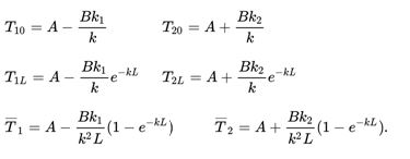
Choosing any two of the temperatures above eliminates the constants of integration, letting us find the other four temperatures. We find the total energy transferred by integrating the expressions for the time rate of change of internal energy per unit length:
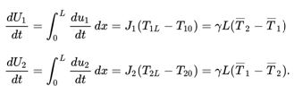
By the conservation of energy, the sum of the two energies is zero. The quantity ![]() is known as the Log mean temperature difference, and is a measure of the effectiveness of the heat exchanger in transferring heat energy.
is known as the Log mean temperature difference, and is a measure of the effectiveness of the heat exchanger in transferring heat energy.