Portable air conditioners use the vapour compression cycle to produce cold air. Here we detail how this process works.
At Broughton EAP we manufacture portable industrial air conditioning units, portable electric heaters such as fan and infra red heaters, refrigerant dehumidifiers (which also use the vapour compression cycle) and cooling and ventilation fans. For details on our full product range then please visit www.broughtoneap.co.uk or call our expert sales team on 01527 830610.
9.1 REFRIGERATION AND REFRIGERATION SYSTEMS
Refrigeration is defined as the process of extracting heat from a lower-temperature heat source, substance, or cooling medium and transferring it to a higher-temperature heat sink. Refrigeration maintains the temperature of the heat source below that of its surroundings while transferring the extracted heat, and any required energy input, to a heat sink, atmospheric air, or surface water. A refrigeration system is a combination of components and equipment connected in a sequential order to produce the refrigeration effect. The refrigeration systems commonly used for air conditioning, including portable air conditioning units, can be classified by the type of input energy and the refrigeration process as follows:
- Vapor compression systems. In vapour compression systems, compressors activate the refrigerant by compressing it to a higher pressure and higher temperature level after it has produced its refrigeration effect. The compressed refrigerant transfers its heat to the sink and is condensed to liquid form. This liquid refrigerant is then throttled to a low-pressure, lowtemperature vapour to produce refrigerating effect during evaporation. Vapour compression systems are the most widely adopted refrigeration systems in both comfort, such as portable air conditioning units, and process air conditioning.
- Absorption systems. In an absorption system, the refrigeration effect is produced by thermal energy input. After absorbing heat from the cooling medium during evaporation, the vapour refrigerant is absorbed by an absorbent medium. This solution is then heated by direct-fired furnace, waste heat, hot water, or steam. The refrigerant is again vaporized and then condensed to liquid to begin the refrigeration cycle again.
- Air or gas expansion systems. In an air or gas expansion system, air or gas is compressed to a high pressure by mechanical energy. It is then cooled and expanded to a low pressure. Because the temperature of air or gas drops during expansion, a refrigeration effect is produced.
Refrigerants, Cooling Media, and Liquid Absorbents
Refrigerants. A refrigerant is the primary working fluid used for absorbing and transmitting heat in a refrigeration system. Refrigerants absorb heat at a low temperature and low pressure and release heat at a higher temperature and pressure. Most refrigerants undergo phase changes during heat absorption—evaporation—and heat releasing—condensation.
Cooling Media. A cooling medium is the working fluid cooled by the refrigerant to transport the cooling effect between a central plant and remote cooling units and terminals. In a large, centralized system, it is often more economical to use a coolant medium that can be pumped to remote locations where cooling is required. Chilled water, brine, and glycol are used as cooling media in many refrigeration systems. The cooling medium is often called a secondary refrigerant, because it obviates extensive circulation of the primary refrigerant.
Liquid Absorbents. A solution known as liquid absorbent is often used to absorb the vaporized refrigerant (water vapor) after its evaporation in an absorption refrigeration system. This solution, containing the absorbed vapor, is then heated at high pressure. The refrigerant vaporizes, and the solution is restored to its original concentration for reuse. Lithium bromide and ammonia, both in a water solution, are the liquid absorbents used most often in absorption refrigerating systems.
Azeotropic, Near Azeotropic, and Zeotropic
A refrigerant can either be a single chemical compound or a mixture (blend) of multiple compounds.
Azeotropic. These are blends of multiple components of volatilities (refrigerants) that evaporate and condense as a single substance and do not change their volumetric composition or saturation temperature when they evaporate or condense at a constant pressure. Components in a mixture of azeotropes cannot be separated from their constituents by distillation. Properties of azeotropic refrigerants are entirely different from those of their components and may be conveniently treated as a single chemical compound.
Near Azeotropic. Near-azeotropic refrigerants are blends whose characteristics are near to azeotropic. Although properties of near-azeotropic refrigerants are nearer to azeotropic than to nonazeotropic (zeotropic), near-azeotropic refrigerants are defined as zeotropic or nonazeotropic.
Zeotropic. These are blends of multiple components of volatilities (refrigerants) that evaporate and condense as a single substance and do change volumetric composition or saturation temperature when they evaporate or condense at a constant pressure.
Blends. Mixtures of refrigerants of two or more chemical compounds are blends. The advantage of a blend of multiple chemical compounds compared to a single compound is that the required properties of the blend can possibly be achieved by varying the fractional composition of the components.
Glide. Zeotropic mixtures, including near-azeotropic blends, show changes in composition because of the leaks, the difference between liquid and vapour phases, or the difference between the charge and circulation, or their combined effect. The shift in composition causes the change in evaporating and condensing temperature and pressure. The difference in dew point and bubble point in the temperature-concentration diagram of a zeotropic refrigerant during evaporation and condensation is called glide, expressed in °F (°C). A near-azeotropic refrigerant has a smaller glide than a zeotropic one. The midpoint between the dew point and bubble point is usually taken as the evaporating or condensing temperature for a nonazeotropic and near-azeotropic refrigerant. Hwang et al. (1997) showed that temperature drops during condensation and temperature increases during evaporation. Ideal or perfect azeotropic refrigerants are uncommon, whereas near-azeotropic ones are fairly common.
Numbering of Refrigerants
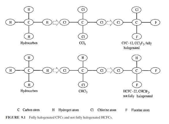
Before the invention of chlorofluorocarbons (CFCs), refrigerants were called by their chemical names. Because of the complexity of these names, especially the CFCs, the fully halogenated CFCs, and hydrochlorofluorocarbons (HCFCs), the not fully halogenated HCFCs (see Fig. 9.1), a numbering system was developed for hydrocarbons and halocarbons, and is used widely in the refrigeration industry. According to ANSI/ASHRAE Standard 34-1997, the first digit from the right is the number of fluorine atoms in the compound. The second digit from the right is one more than the number of hydrogen atoms in the compound. The third digit from the right is one less than the number of the carbon atoms in the compound. If the digit is zero, it is omitted from the number. The fourth digit from the right is the number of unsaturated carbon-carbon bonds in the compound. If the digit is zero it is also omitted from the number. For example, the chemical formula of HCFC-123 is CHCl2CF3:
There are 3 fluorine atoms, first digit from the right is 3
There is 1 hydrogen atom, second digit from the right is 1 + 1 – 2
There are 2 carbon atoms, third digit from the right is 2 – 1 – 1
No unsaturated C9C bonds, the fourth digit from the right is 0
9.3 PROPERTIES AND CHARACTERISTICS OF REFRIGERANTS
Today, the preservation of the ozone layer is the first priority of refrigerant selection. In addition,
the global warming effect and the following factors should be considered.
Safety Requirements
Refrigerant may leak from pipe joints, seals, or component parts during installation, operation, or
accident. Therefore, refrigerants must be acceptably safe for humans and manufacturing processes,
with little or no toxicity or flammability.
In ANSI/ASHRAE Standard 34-1997, the toxicity of refrigerants is classified as class A or B.
Class A refrigerants are of lower toxicity. A class A refrigerant is one whose toxicity has not been
identified when its concentration is less than or equal to 400 ppm, based on threshold limit
value–time-weighted average (TLV-TWA) or equivalent indices. The TLV-TWA concentration is a
concentration to which workers can be exposed over an 8-h workday and a 40-h workweek without
suffering adverse effect. Concentration ppm means parts per million by mass.
Class B refrigerants are of high toxicity. A class B refrigerant produces evidence of toxicity
when workers are exposed to a concentration below 400 ppm based on a TLV-TWA concentration.
Flammable refrigerants explode when ignited. If a flammable refrigerant is leaked in the area of a
fire, the result is an immediate explosion. Soldering and welding for installation or repair cannot be
performed near such gases.
ANSI/ASHRAE Standard 34-1997 classifies the flammability of refrigerants into classes 1, 2,
and 3. Class 1 refrigerants show no flame propagation when tested in air at a pressure of 14.7 psia
(101 kPa) at 65°F (18.3°C). Class 2 refrigerants have a lower flammability limit (LFL) of more than
0.00625 lb/ ft3 (0.1 kg/m3) at 70°F (21.1°C) and 14.7 psia (101 kPa abs.), and a heat of combustion
less than 8174 Btu/lb (19,000 kJ/kg). Class 3 refrigerants are highly flammable, with an LFL less
than or equal to 0.00625 lb/ ft3 (0.1 kg/m3) at 70°F (21.1°C) and 14.7 psia (101 kPa abs.) or a heat
of combustion greater than or equal to 8174 Btu /lb (19,000 kJ/ kg).
A refrigerant’s safety classification is its combination of toxicity and flammability. According to
ANSI/ASHRAE Standard 34-1997, safety groups are classified as follows:
A1 lower toxicity and no flame propagation
- _ A2 lower toxicity and lower flammability
- _ A3 lower toxicity and higher flammability
- _ B1 higher toxicity and no flame propagation
- _ B2 higher toxicity and lower flammability
- _ B3 higher toxicity and higher flammability
For zeotropic blends whose flammability and toxicity may change as their composition changes, a
dual safety classification should be determined. The first classification denotes the classification of
the formulated composition of the blend. The second classification lists the classification of the
blend composition at the worst case of fractionation.
Effectiveness of Refrigeration Cycle
The effectiveness of refrigeration cycles, or coefficient of performance (COP), is one parameter that
affects the efficiency and energy consumption of the refrigeration system. It will be clearly defined
in a later section. The COP of a refrigeration cycle using a specific refrigerant depends mainly upon
the isentropic work input to the compressor at a given condensing and evaporating pressure differential,
as well as the refrigeration effect produced.
Evaporating and Condensing Pressures
It is best to use a refrigerant whose evaporating pressure is higher than that of the atmosphere so
that air and other noncondensable gases will not leak into the system and increase the condensing
pressure. The condensing pressure should be low because high condensing pressure necessitates
heavier construction of the compressor, piping, condenser, and other components. In addition, a
high-speed centrifugal compressor may be required to produce a high condensing pressure.
Oil Miscibility
When a small amount of oil is mixed with refrigerant, the mixture helps to lubricate the moving
parts of a compressor. Oil should be returned to the compressor from the condenser, evaporator, accessories,
and piping, in order to provide continuous lubrication. On the other hand, refrigerant can
dilute oil, weakening its lubricating effect; and when the oil adheres to the tubes in the evaporator
or condenser, it forms film that reduces the rate of heat transfer.
Inertness
An inert refrigerant does not react chemically with other materials, thus avoiding corrosion, erosion,
or damage to the components in the refrigerant circuit.
Thermal Conductivity
The thermal conductivity of a refrigerant is closely related to the efficiency of heat transfer in the
evaporator and condenser of a refrigeration system. Refrigerant always has a lower thermal conductivity
in its vapour state than in its liquid state. High thermal conductivity results in higher heat transfer
in heat exchangers.
Refrigeration Capacity
The cubic feet per minute (cfm) suction vapor of refrigerant required to produce 1 ton of refrigeration
(liters per second to produce 1 kW of refrigeration) depends mainly on the latent heat of vaporization
of the refrigerant and the specific volume at the suction pressure. It directly affects the size
and compactness of the compressor and is one of the criteria for refrigerant selection.
Physical Properties
Discharge Temperature. A discharge temperature lower than 212°F (100°C) is preferable because
temperatures higher than 300°F (150°C) may carbonize lubricating oil or damage some of the
components.
Dielectric Properties. Dielectric properties are important for those refrigerants that will be in direct
contact with the windings of the motor (such as refrigerants used to cool the motor windings in
a hermetically sealed compressor and motor assembly).
Operating Characteristics
Leakage Detection. Refrigerant leakage should be easily detected. If it is not, gradual capacity reduction
and eventual failure to provide the required cooling will result. Most of the currently used
refrigerants are colourless and odourless.
9.4 PHASEOUT OF OZONE DEPLETION REFRIGERANTS
Refrigerant Use
The use of CFCs and HCFCs is a global concern. Approximately two-thirds of all fully halogenated
CFCs were used outside the United States in the mid-1980s. In 1985, the total use of halocarbons
in the United States was 611 million lb (0.28 million ton). These halocarbons were used in foam insulation,
automotive air conditioners, new systems of Air Conditioning and Refrigeration Institute
(ARI) members, and other products. Foam insulation blown by CFCs was the largest user. Automotive
air conditioners made up 19 percent of the total and CFCs purchased by ARI members for new
systems made up 5 percent of the total use. Of the CFCs and HCFCs purchased by ARI members,
HCFC-22 made up 77 percent, while CFC-11 and CFC-12 each made up about 10 percent.
Ozone Depletion and Global Warming Potentials
To compare the relative ozone depletion caused by various refrigerants, an index called the ozone
depletion potential (ODP) has been proposed. ODP is the ratio of the rate of ozone depletion of 1 lb
of any halocarbon to that of 1 pound of CFC-11. The ODP of CFC-11 is assigned a value of 1. The
following are the ODP values for various refrigerants:
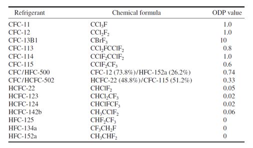
Similar to the ODP, the halocarbon global warming potential (HGWP) is the ratio of calculated
warming for each unit mass of gas emitted to the calculated warming for a unit mass of reference
gas CFC-11. The HGWPs of various refrigerants are listed in Table 9.1. In addition to the HGWP,
another global warming index uses CO2 as a reference gas. For example, 1 lb of HCFC-22 has the same effect on global warming as 4100 lb (1860 kg) of CO2 in the first 20 years after it is released
into the atmosphere. Its impact drops to 1500 lb (680 kg) at 100 years.
Phaseout of CFCs, Halons, and HCFCs
The theory of depletion of the ozone layer was proposed in 1974 by Rowland and Molina. (The
1995 Nobel Prize was awarded to F. Sherwood Rowland, Mario Molina, and Paul Crutzen for their
work in atmospheric chemistry and theory of ozone depletion.) Network station in Halley Bay,
Antarctica, established a baseline trend of ozone levels that helped scientists to discover the ozone
hole in 1985. National Aeronautics and Space Administration (NASA) flights into the stratosphere
over the arctic and antarctic circles found CFC residue where the ozone layer was damaged. Approximately
the same ozone depletion over the antarctic circle was found in 1987, 1989, 1990, and
- By 1988, antarctic ozone levels were 30 percent below those of the mid-1970s. The most severe
ozone loss over the antarctic was observed in 1992. Ground monitoring at various locations
worldwide in the 1980s has showed a 5 to 10 percent increase in ultraviolet radiation. Although
there is controversy about the theory of ozone layer depletion among scientists, as discussed in
Rowland (1992), action must be taken immediately before it is too late.
Montreal Protocol and Clean Air Act
In 1978, the Environmental Protection Agency (EPA) and the Food and Drug Administration (FDA)
of the United States issued regulations to phase out the use of fully halogenated CFCs in nonessential
aerosol propellants, one of the major uses at that time. On September 16, 1987, the European
Economic Community and 24 nations, including the United States, signed the Montreal Protocol.
This document is an agreement to phase out the production of CFCs and halons by the year 2000.
The Montreal Protocol had been ratified by 157 parties.
The Clean Air Act Amendments, signed into law in the United States on November 15, 1990,
governed two important issues: the phaseout of CFCs and a ban (effective July 1, 1992) on the deliberate
venting of CFCs and HCFCs. Deliberate venting of CFCs and HCFCs must follow the regulations
and guidelines of the EPA. In February 1992, then-President Bush called for an accelerated
phaseout of the CFCs in the United States. Production of CFCs must cease from January 1, 1996,
with limited exceptions for service to certain existing equipment.
In late November 1992, representatives of 93 nations meeting in Copenhagen also agreed to the
complete cessation of CFC production beginning January 1, 1996, and of halons by January 1,
1994, except continued use from existing (reclaimed or recycled) stock in developed nations. In
addition, the 1992 Copenhagen amendments and later a 1995 Vienna meeting revision agreed to
restrict the production of HCFCs relative to a 1989 level beginning from 2004 in developed nations
according to the following schedule:
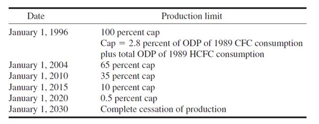
Consumption indicates the production plus imports minus exports and feedstocks. The value of
2.8 percent cap is the revised value of the Vienna meeting in 1995 to replace the original value of 3.1 percent in the Copenhagen amendments. The Copenhagen amendments had been ratified by 58 parties.
Action and Measures
The impact of CFCs on the ozone layer poses a serious threat to human survival. The following
measures are essential:
Conversions and Replacements. Use alternative refrigerants (substitutes) to replace the CFCs in
existing chillers and direct-expansion (DX) systems. During the conversion of the CFC to
non–ozone depletion alternative refrigerants, careful analysis should be conducted of capacity, efficiency,
oil miscibility, and compatibility with existing materials after conversion. For many refrigeration
systems that already have a service life of more than 15 years, it may be cost-effective to
buy a new one using non-CFC refrigerant to replace the existing refrigeration package.
- HFC-134a and HCFC-22 are alternative refrigerants to replace CFC-12.
- HCFC-123, and HFC-245ca are alternative refrigerants to replace CFC-11 in large chillers. It is important to realize that HCFC-123 and HCFC-22 themselves are interim refrigerants and will be restricted in consumption beginning in 2004. HCFC-123 has a very low global warming potential and is widely used in centrifugal chillers. HCFC-22 is widely used in small and medium-size DX systems.
- HFC-134a, HFC-407C, and HFC-410A are alternative refrigerants to replace HCFC-22. HFC-407C is a near-azeotropic refrigerant of HFC-32/HFC-125/HFC-134a (23/25/52) [means (23%/25%/525)], and HFC-410A also a near-azeotropic refrigerant of HFC-32/HFC-125 (50/50).
- HFC-245ca or another new HFC possibly developed before 2004 will be the hopeful alternative to replace HCFC-123. In supermarkets, CFC-502 is a blend of HCFC-22/CFC-115 (48.8/ 51.2).
- HFC-404A, HFC-507, and HFC-410A are alternative refrigerants to replace CFC-502. HFC-404A is a near-azeotropic refrigerant of HFC-125/HFC-143a/HFC-134a(44/52/4); and HFC-507 is an azeotropic refrigerant of HFC-125/HFC-143a (45/ 55).
Reducing Leakage and Preventing Deliberate Venting. To reduce the leakage of refrigerant from
joints and rupture of the refrigeration system, one must detect the possible leakage, tighten the
chillers, improve the quality of sealing material, and implement preventive maintenance.
Prevent the deliberate venting of CFCs and HCFCs and other refrigerants during manufacturing,
installation, operation, service, and disposal of the products using refrigerants.
Avoid CFC and HCFC emissions through recovery, recycle, and reclaiming. According to
ASHRAE Guideline 3-1990, recovery is the removal of refrigerant from a system and storage in an
external container. Recycle involves cleaning the refrigerant for reuse by means of an oil separator
and filter dryer. In reclamation, refrigerant is reprocessed for new product specifications.
To avoid the venting of CFCs and HCFCs and other refrigerants, an important step is to use an
ARI-certified, portable refrigerant recovering/ recycling unit to recover all the liquid and remaining
vapor from a chiller or other refrigeration system. An outside recovery/ reclaiming service firm may
also be employed. A typical refrigerant recovery unit is shown in Fig. 9.2. It includes a recovery
cylinder, a vacuum pump or compressor, a water-cooled condenser, a sight glass, a shutoff float
switch, necessary accessories, pipes, and hoses.
To recover refrigerant from a chiller that has been shut down involves two phases: liquid recovery
and vapor recovery. Liquid recovery is shown in Fig. 9.2a. The vacuum pump or compressor
in the recovery unit creates a low pressure in the recovery cylinder. Liquid refrigerant is then
extracted from the bottom of the chiller into the recovery cylinder. If the recovery cylinder is not
large enough, the shutoff float switch ceases to operate the vacuum pump or compressor when the recovery cylinder is 80 percent full. Another empty recovery cylinder is used to replace the filled
cylinder. If the vapour enters the sight glass, which means that the liquid refrigerant is all extracted,
then the vacuum pump or compressor is stopped and the vapour recovery phase begins.
Vapour recovery is shown in Fig. 9.2b. The vacuum pump or compressor extracts the refrigerant
vapour from the top of the chiller. Extracted refrigerant vapour is then condensed to liquid form that
flows through the water-cooled condenser and is stored in the recovery cylinder. Noncondensable
gases are purged into the atmosphere from the recovery unit. Water at a temperature between 40
and 85°F (4.4 and 29.4°C) is often used as the condensing cooling medium. The recovered refrigerant
can be recycled or reclaimed as required.
In addition to the recovery of refrigerants from the chiller or other refrigeration system, refrigerant
vapour detectors should be installed at locations where refrigerant from a leak is likely to
concentrate. These detectors can set off an alarm to notify the operator to seal the leak.

Because of the worldwide effort to phase out CFCs, the latest result of a study conducted by the
National Oceanic and Atmospheric Administration (NOAA) and published in the journal Science
was reported by UPI science writer Susan Milius “. . . scientists are cheering a 1 percent reduction
during 1995 in the chemicals that slowly carry chlorine and bromine aloft to the stratosphere.”
(Air Conditioning, including portable air conditioning units, Heating and Refrigeration News, June 10, 1996, p. 2).
Status of CFC Replacements
Dooley (1997) showed that according to the ARI survey, in the United States there were about
80,000 CFC large-tonnage chillers in 1992, and most used CFC-11 as refrigerant. At the beginning
of 1997, some 18,981 chillers, or 24 percent of the total 80,000, had been phased-out CFC refrigerants.
Of these, 4813 chillers were converted to non-CFC refrigerant, and 14,168 chillers were
replaced by new chillers which used non-CFC refrigerant. The ratio of new replacements to conversions
was about 3 to 1. It is often cost-effective to replace an old chiller instead of to convert the
CFC refrigerant to alternatives in an existing chiller.
The ARI estimates that 53 percent of the 80,000 chillers in 1992 will remain in service on
January 1, 2000. This shows that the actual phaseout process was slower than expected.
For CFC-12, automotive cooling and supermarkets account for more than 90 percent of their servicing
requirements. Due to the vibrations and unsteady operating conditions, automotive cooling
required greater servicing losses and a faster phaseout schedule than large-tonnage chillers. The annual
amount of CFCs required to compensate for servicing losses came from stockpiles of virgin
CFCs and reclaimed CFCs. Because of the slower phaseout of CFC chillers, servicing demands
were greater than could be supplied from the reclaimed CFCs. The using up of the stockpiles of
virgin CFCs and thus a shortage of CFC supply may occur at the beginning of the twenty-first century
in the United States. The slower phaseout of CFCs indicated that there is a possibility of a
considerably longer period of servicing of HCFC equipment than called for in the production
phaseout schedule in the twenty-first century.
9.5 CLASSIFICATION OF REFRIGERANTS
Before the introduction of chlorofluorocarbons in the 1930s, the most commonly used refrigerants
were air, ammonia, sulphur dioxide, carbon dioxide, and methyl chloride. Until 1986, nontoxic
and nonflammable halogenated hydrocarbons with various ozone depletion potentials were used
almost exclusively in vapour compression refrigeration systems for air conditioning, such as portable air conditioning units. The impact of
ozone depletion of CFCs, halons, and HCFCs since the 1980s caused a worldwide decision to
phase out these refrigerants. A new classification of refrigerants into six groups based mainly on
ozone depletion will be helpful for the selection of non–ozone depletion refrigerants as well as
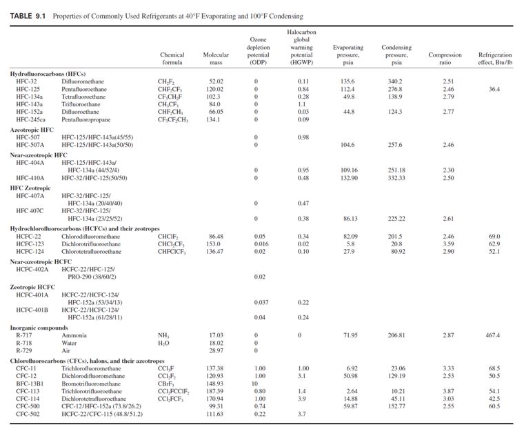
replacement of CFCs by alternative refrigerants (Table 9.1).
Hydrofluorocarbons
HFCs contain only hydrogen, fluorine, and carbon atoms. They contain no chlorine atoms, therefore
are environmentally safe, and cause no ozone depletion. They are designated by the prefix HFC.
HFC-134a is an attractive, long-term alternative to replace CFC-12 in reciprocating, scroll,
screw, and centrifugal compressors; and a long-term alternative for HCFC-22. It has a low 0.28
HGWP. HFC-134a is nonflammable, has an extremely low toxicity, and is classified as AI in
ANSI/ASHRAE Standard 34-1997 safety rating.
HFC-134a has a molecular mass of 102.3 instead of CFC-12’s molecular mass of 120.93. At a
condensing temperature of 100°F (37.8°C), HFC-134a’s condensing pressure is 138.83 psia (957
kPa abs.), whereas CFC-12’s is 131.65 psia (908 kPa abs.). A larger impeller of higher speed is needed for a centrifugal chiller to provide the same cooling capacity. Parsnow (1993) reported a
capacity loss of direct conversion from CFC-12 to HFC-134a of 8 to 10 percent, and an efficiency
loss of 1 to 2 percent. In Lowe and Ares (1995), in the conversion from CFC-12 to HFC-134a in the
Sears Tower centrifugal chillers, the compressor’s speed increased about 8.5 percent, there was a
cooling capacity loss of 12 to 24 percent, and efficiency was 12 to 16 percent worse.
HFC-134a has a poor mutual solubility with mineral oil because of a higher interfacial tension
between them. Polyolester-based synthetic lubricants should be used. Polyolester-based synthetic
oils are hygroscopic, so monitoring of the moisture content of the refrigerant is important. Halocarbons,
including HFC-134a, are compatible with containment materials. Concerning nonmetallic or
elastomer (such as gaskets) compatibility, Corr et al. (1993) reported that HFC-134a, an ester-based
synthetic oil mixture, has a smaller volume change of elastomer than CFC-12 and mineral oil.
HFC-134a may become one of the most widely used single-chemical-compound refrigerants during
the first half of the twenty-first century.
HFC-245ca also does not contain chlorine and bromine atoms, and its ODP is 0. Compared to
CFC-11, its efficiency will be 3 to 4 percent lower. Synthetic polyolester lubricant oil will be used.
Except for neoprene at high moisture content, common materials used in the refrigeration system
were shown to be compatible with HFC-245ca in tests. Smith et al. (1993) reported that mixtures of
HFC-245ca in air with a relative humidity of 43 percent and a HFC-245ca concentration range of
7 to 14.4 percent were observed to be flammable in tests.
Because of the higher isentropic work required by HFC-245ca compared to CFC-11 and HCFC-
123, for direct-drive centrifugal chillers, a large impeller is required during the conversion from
CFC-11 to HFC-245ca or from HCFC-123 to HFC-245ca.
HFC-245ca is a possible long-term alternative to CFC-11 and HCFC-123 in large centrifugal
chillers in the future. In the HFC group, HFC-32, HFC-125, HFC-143a, and HFC-152a all are seldom
used as a refrigerant of single compound only.
Azeotropic HFC
HFC-507 is an azeotrope of refrigerant blends of HFC-125/HFC-143a (45/55) of zero ozone
depletion and an HGWP of 0.96. It is a long-term alternative refrigerant to replace CFC-502 and
CFC-12 in low-temperature refrigeration systems whose evaporating temperatures are below 10°F
( 12.2°C). HFC-507 needs synthetic lubricant oil. According to ANSI/ASHRAE Standard 34-
1997, HFC-507 is allowed alternative designations for HFC-507A, a refrigeration blend of HFC-
125/HFC-143a (50/ 50).
The Linton et al. (1995) test results showed that compared to CFC-502, the cooling capacity of
HFC-507 was between 0.95 and 1.05. HFC-507 had an energy efficiency of 0.87 to 0.97 compared
to CFC-502.
Near-Azeotropic HFC
Near-azeotropic HFC is a refrigerant blend of zero ozone depletion and having rather small changes
in volumetric composition or saturation temperature, a small glide, when it evaporates or condenses
at a constant pressure. Near-azeotropic HFC-404A and HFC-410A require synthetic lubricant oil
instead of mineral oil and are nontoxic and nonflammable with a safety classification of A1/A1.
HFC-404A is a blend of HFC-125/HFC-143a/HFC-134a (44/52/4) of zero ozone depletion
and an HGWP of 0.94. It is a long-term alternative refrigerant for CFC-502 and CFC-12 both in
low-temperature refrigeration systems. HFC-404A has a temperature glide of 0.9°F (0.5°C) during
evaporation and a temperature glide of 0.6°F (0.33°C) during condensation. Snelson et al. (1995)
compared HFC-404A with CFC-502 from their test results. HFC-404A had the same, slightly
higher, or lower evaporating capacity at various condensing and evaporating temperatures. The energy
efficiency ratio of 0.89 to 0.99 was found at different evaporating temperatures Tev. The lower
the Tev, the lower the energy efficiency ratio, because of the higher compressor pressure ratio.
HFC-410A is a blend of HFC-32/HFC-125 (50/50) of zero ozone depletion and an HGWP of
0.43. It is a long-term alternative refrigerant to replace HCFC-22 and CFC-502. HFC-410A has a
temperature glide of 0.2°F (0.11°C) during evaporation and condensation. Hickman (1994) showed
that the compressor displacement, cfm/ton (L/ s kW), for HFC-410A is about 50 percent smaller
than that for HCFC-22; and the discharge pressure for 130°F (54.4°C) condensing is about 490 psia
(3379 kPa abs.), which is much higher than that for HCFC-22. It is often necessary to change the
original reciprocating compressor to a scroll compressor. A higher energy efficiency was reported
by a refrigerant manufacturer.
Zeotropic HFC
Zeotropic (nonazeotropic) HFCs are refrigerant blends of zero ozone depletion that have greater
temperature glide during evaporation and condensation. Zeotropic HFC-407A and HFC-407C also
require synthetic lubrication oil, instead of mineral oil; and both are nontoxic and nonflammable
with a safety classification of A1/A1.
HFC-407A is a blend of HFC-32/HFC-125/HFC-134a (20/40/40) of zero ozone depletion
with an HGWP of 0.49. It is a long-term alternative refrigerant for CFC-502 and CFC-12 in lowtemperature
refrigeration systems. HFC-407A showed a reduction in heat transfer in the evaporator
of a low-temperature system during tests. The system performance of HFC-407A was the lowest
compared to HFC-404A and HFC-507.
HFC-407C is a blend of HFC-32/HFC-125/134a (23/25/52) of zero ozone depletion with an
HGWP of 0.38. It is a long-term alternative refrigerant to replace HCFC-22 and CFC-502. Bivens
et al. (1994) compared HFC-407C to HCFC-22 during tests. For cooling and heating, the capacity
ratio ranged from 0.93 to 1.06, and the energy ratio ranged from 0.94 to 0.97. In-tube heat-transfer
coefficients during evaporation and condensation were 85 to 95 percent of HCFC-22 values.
HCFCs and Their Zeotropes
HCFCs contain hydrogen, chlorine, fluorine, and carbon atoms and are not fully halogenated.
HCFCs have a much shorter atmospheric life than CFCs and cause far less ozone depletion (0.02 to
0.1 ODP). They are designated by the prefix HCFC. Their consumption is scheduled to be reduced
gradually starting from 2004 and will be completely phased out in 2030 in developed nations, except
for a limited amount for service, as discussed previously.
HCFC-22 has an ODP of 0.05 and an HGWP of 0.40. It is nonflammable with a safety classification
of A1. HCFC-22 is partially miscible with mineral oil. At 40°F (4.4°C), its evaporating pressure
is 82.09 psia (566 kPa abs.), and at 100°F (37.8°C) its condensing pressure is 201.5 psia (1389
kPa abs.), the highest of currently used HCFC and CFC refrigerants. HCFC-22 has a smaller compressor
displacement among the HCFCs and CFCs. All these factors make it an interim alternative
to replace CFC-12. HCFC-22 was the most widely used refrigerant in reciprocating and scroll compressors
in small and medium-size packaged units in the 1990s in the United States.
HCFC-123 is an interim alternative to replace CFC-11 in low-pressure centrifugal chillers. It has
an ODP of 0.02 and a very low HGWP of 0.02. HCFC-123 is nonflammable and of lower toxicity
with a safety classification of B1. In 1997, DuPont raised the allowable exposure limit (AEL) of
HCFC-123 to 50 ppm. Smithhart and Crawford (1993) reported that for chillers with direct conversion
from CFC-11 to HCFC-123, there was about a decrease of 0 to 5 percent in capacity and a 2 to
4 percent decrease in efficiency. A conversion of refrigerant from CFC-11 to HCFC-123 in an existing
chiller may require changing its lubricants, seals, and motor windings of hermetic compressors.
Because HCFC-123 has a low ODP, a very low HGWP, and a 15 percent higher energy efficiency
in centrifugal chillers than HFC-134a does, if no acceptable alternative can be found, the use
of HCFC-123 in centrifugal chillers may be considered longer than the cap specified in the Vienna
meeting in 1995, as listed in Sec. 9.4, in the twenty-first century.
HCFC-124 has an ODP of 0.02. It is nonflammable and has a safety classification of A1. HCFC-
124 is an interim alternative refrigerant to replace CFC-114.
Near-azeotropic HCFC-402A is a blend of HCFC-22/HFC-125/PRO-290 (38/60/2) with an
ODP of 0.02 and an HGWP of 0.63. Here PRO-290 represents propane, which is a more highly
flammable refrigerant with a safety classification of A3. HCFC-402A is nonflammable and has a
safety classification of A1/A1. It needs polyolester or alkyl-benzene-based lubricant oil. HCFC-
402A is an interim alternative refrigerant to replace CFC-502.
Zeotropic HCFC-401A is a blend of HCFC-22/HCFC-124/HFC-152a (53/34/13) with an ODP
of 0.037 and an HGWP of 0.22; and HCFC-401B is a blend of HCFC-22/HCFC-124/HFC-152a
(61/28/11) with an ODP of 0.04 and an HGWP of 0.24. Both HCFC-401A and HCFC-401B are
nonflammable and have a safety classification of A1/A1. They both need alkyl-benzene-based lubricant
oil. HCFC-401A is an interim alternative refrigerant to replace CFC-12, and HCFC-401B is an
interim alternative refrigerant to replace CFC-12 in low-temperature refrigeration systems.
Inorganic Compounds
These compounds include ammonia (NH3), water (H2O), and gases used in the gas expansion systems.
As refrigerants, they were used far earlier than the halocarbons. Air is a mixture of nitrogen,
oxygen, argon, rare gases, and water vapour. Air has zero ozone depletion and is a zeotropic blend that
has a temperature glide of 5.5°F (3°C) at atmospheric pressure. Ammonia also has zero ozone
depletion. It has a high operating pressure at 40°F (4.4°C) evaporating and 100°F (37.8°C) condensing.
Ammonia compressors show a smaller cfm/ton displacement and higher energy efficiency than
HCFC-22 compressors. Leakage of ammonia is easily detected due to its objectionable odour.
Ammonia attacks copper even in the presence of a small amount of moisture. It is of higher toxicity.
An ammonia-air mixture is flammable if the concentration of NH3 by volume is within 16 to
25 percent. The mixture may explode if the ignition source is above 1200°F (650°C). Because the
safety classification of ammonia is B2—lower flammability and higher toxicity—it is not allowed
to be used in comfort air conditioning such as portable air conditioning units in the United States.
Water has a zero ODP and is readily available. At 40°F (4.4°C) evaporating and 100°F (37.8°C)
condensing, water’s evaporating and condensing pressures are both below atmospheric. Air and
other noncondensable gases must be purged out of the refrigeration system periodically.
CFCs, Halons, and Their Zeotropes
CFCs including CFC-11, CFC-12, CFC-113, and CFC-114, have an ODP from 0.8 to 1.0. Halons
including BFC-13B1 have an ODP of 10. Their azeotropics CFC-500 and CFC-502 have ODPs of
0.74 and 0.22, respectively. Production of all these CFCs, halons, and their azeotropes ceased in developed
nations since January 1, 1996. However, a limited amount of these refrigerants, used to service
the refrigeration systems that have not been converted or replaced by non–ozone depletion refrigerants,
may be extended to the beginning of the twenty-first century.
9.6 REFRIGERATION PROCESSES AND REFRIGERATION CYCLES
Refrigeration Processes
A refrigeration process indicates the change of thermodynamic properties of the refrigerant and the
energy transfer between the refrigerant and the surroundings. The following refrigeration processes
occur during the operation of a vapour compression refrigerating system:
- In this process, the refrigerant evaporates at a lower temperature than that of its
surroundings, absorbing its latent heat of vaporization.
- Saturated refrigerant vapour is usually superheated to ensure that liquid refrigerant
does not flow into the compressor.
- Refrigerant is compressed to a higher pressure and temperature for condensation.
- Gaseous refrigerant is condensed to liquid form by being desuperheated, then condensed,
and finally subcooled, transferring its latent heat of condensation to a coolant.
- Throttling and expansion. The higher-pressure liquid refrigerant is throttled to the lower evaporating
pressure and is ready for evaporation.
The following refrigeration processes occur during the operation of an air or gas expansion
refrigeration system:
- Air or gas is compressed to a higher pressure and temperature.
- Heat release. Heat is released to the surroundings at constant pressure in order to reduce the temperature
of the air or gas.
- Throttling and expansion. Air or gas is throttled and expanded so that its temperature is lowered.
- Heat absorption. Heat is absorbed from the surroundings because of the lower air or gas temperature.
Refrigeration Cycles
Most refrigerants undergo a series of evaporation, compression, condensation, throttling, and expansion
processes, absorbing heat from a lower-temperature reservoir and releasing it to a highertemperature
reservoir in such a way that the final state is equal in all respects to the initial state. It is
said to have undergone a closed refrigeration cycle. When air or gas undergoes a series of compression,
heat release, throttling, expansion, and heat absorption processes, and its final state is not
equal to its initial state, it is said to have undergone an open refrigeration cycle.
Both vapor compression and air or gas expansion refrigeration cycles are discussed in this chapter.
Absorption refrigeration cycles are covered in Chap. 14.
Unit of Refrigeration
In inch-pound (I-P) units, refrigeration is expressed in British thermal units per hour, or simply Btu/h.
A British thermal unit is defined as the amount of heat energy required to raise the temperature of one
pound of water one degree Fahrenheit from 59°F to 60°F; and 1 Btu/h 0.293 watt (W).
Another unit of refrigeration widely used in the HVAC&R industry is ton of refrigeration, or
simply ton. As mentioned before, 1 ton 12,000 Btu/h of heat removed. This equals the heat
absorbed by 1 ton (2000 lb) of ice melting at a temperature of 32°F over 24 h.
Because the heat of fusion of ice at 32°F is 144 Btu / lb:
1 ton = (1 X 2000 X 144)/24 = 12,000 Btu/hr, also 1 ton = 3.516 kW.
9.7 GRAPHICAL AND ANALYTICAL EVALUATION OF REFRIGERATION
Pressure-Enthalpy Diagram
The pressure-enthalpy p-h diagram is the most common graphical tool for analysis and calculation
of the heat and work transfer and performance of a refrigeration cycle. A single-stage refrigeration
cycle consists of two regions: the high-pressure region, or high side, and the low-pressure region, or
low side. The change in pressure can be clearly illustrated on the p-h diagram. Also, both heat and
work transfer of various processes can be calculated as the change of enthalpy and are easily shown
on the p-h diagram.
Figure 9.3 is a skeleton p-h diagram for refrigerant HCFC-22. Enthalpy h (in Btu/ lb) is the
abscissa, and absolute pressure (psia) or gauge pressure (psig), both expressed in logarithmic scale,
is the ordinate. The saturated liquid line separates the subcooled liquid from the two-phase region in
which vapour and liquid refrigerants coexist. The saturated vapour line separates this two-phase
region from the superheated vapour. In the two-phase region, the mixture of vapour and liquid is
subdivided by the constant-dryness-fraction quality line.
The constant-temperature lines are nearly vertical in the subcooled liquid region. At higher temperatures,
they are curves near the saturated liquid line. In the two-phase region, the constant-temperature
lines are horizontal. In the superheated region, the constant-temperature lines curve down
sharply. Because the constant-temperature lines and constant-pressure lines in the two-phase region
are horizontal, they are closely related. The specific pressure of a refrigerant in the two-phase
region determines its temperature, and vice versa.
Also in the superheated region, the constant-entropy lines incline sharply upward, and constantvolume
lines are flatter. Both are slightly curved.

FIGURE 9.3 Skeleton of pressure-enthalpy p-h diagram for HCFC-22.
Temperature-Entropy Diagram
The temperature-entropy T-s diagram is often used to analyze the irreversibilities in a refrigeration
cycle, as well as in the system, in order to select optimum operating parameters and improve performance
of the system. In a temperature-entropy T-s diagram, entropy s, Btu / lb°R, is the abscissa of the diagram and temperature T, °R, is the ordinate. A T-s diagram is more suitable for evaluating
the effectiveness of an air expansion refrigeration cycle.
Analytical Evaluation of Cycle Performance
Swers et al. (1972) proposed a thermodynamic analysis of degradation of available energy and irreversibility
in a refrigerating system, and Tan and Yin (1986) recommended a method of exergy
analysis. The exergy of a working substance e, Btu / lb (kJ / kg), is defined as:
e = h – ha – TRa (s – sa) (9.1)
where h, ha = enthalpy of working substance and ambient state, Btu / lb (kJ /kg)
TRa = absolute temperature of ambient state, °R (K)
s, sa = entropy of working substance and ambient state, Btu / lb∙°R (kJ/kg∙K)
Both analyses are effective tools in the selection of optimum design and operating parameters by
means of complicated analysis. They require extensive supporting data and information.
For most analyses of refrigeration cycle performance and design and operation of refrigeration
systems in actual applications, satisfactory results can be obtained by using the steady flow energy
equation, heat and work transfer, and energy balance principle. If a more precise and elaborate
analysis is needed in research or for detailed improvements of refrigeration systems, the references
at the end of this chapter can be consulted.
9.8 CARNOT REFRIGERATION CYCLE
The Carnot refrigeration cycle is a reverse engine cycle. All processes in a Carnot refrigeration
cycle are reversible, so it is the most efficient refrigeration cycle.
Figure 9.4a is a schematic diagram of a Carnot cycle refrigerating system, and Fig. 9.4b shows
the Carnot refrigeration cycle using gas as the working substance. This Carnot cycle is composed of
four reversible processes:
- An isothermal process 4-1 in which heat q#1 is extracted at constant temperature TR1 per lb (kg)
of working substance
- An isentropic compression process 1-2
- An isothermal process 2-3 in which q#2 is rejected at constant temperature TR2 per lb (kg) of
working substance
- An isentropic expansion process 3-4
Figure 9.4c shows the Carnot refrigeration cycle using vapour as the working substance. Wet vapour
is the only working substance where heat supply and heat rejection processes can occur easily
at constant temperature. This is because the temperatures of wet vapour remain constant when latent
heat is supplied or rejected.
As in the gas cycle, there are two isothermal processes 4-1 and 2-3 absorbing heat at temperature
TR1 and rejecting heat at TR2, respectively, and two isentropic processes, one for compression
1-2 and another for expansion 3-4.
Performance of Carnot Refrigeration Cycle
According to the first law of thermodynamics, often called the law of conservation of energy, when
a system undergoes a thermodynamic cycle, the net heat supplied to the system is equal to the net
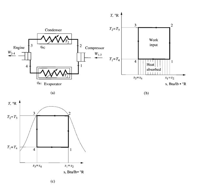
FIGURE 9.4 Carnot refrigeration cycle: (a) schematic diagram; (b) gas cycle; (c) vapour cycle.
work done, or:
Heat supply + heat rejected = net work done (9.2)
Referring to Fig. 9.4a, in a Carnot refrigeration cycle,
q#1– q#2=- W
or,
q#1= q#2– W (9.3)
q#2= q#1+ W
where q#1 = heat supplied from surroundings per lb (kg) of working substance at temperature T1;
sign of q#1 is positive
q#2 = heat rejected to sink per lb (kg) of working substance at temperature T2; sign of q#2
is negative
W = net work done by system; sign is positive, or if it is a work input to system, sign is
Negative
The heat extracted from the source at temperature TR1 by the working substance, i.e., the refrigerating
effect per lb (kg) of working substance, is
q#1= TR1(s1– s4) (9.4)
where s1, s4= entropy at state points 1 and 4, respectively, Btu / lb°R (kJ/kgK). Heat rejected to
the heat sink at temperature TR2 can be calculated as
the ratio of heat rejection to the work input, or
COPhp = q#2 / win (9.9)
For a heat recovery system, the useful effect is q#1 and q#2. In such a condition, COPhr is defined as
the ratio of the sum of the absolute values of refrigerating effect and heat rejection to the absolute
value of the work input, i.e.,
COPhr = │q#1│+ │q#2│/ Win (9.10)
9.10 SINGLE-STAGE IDEAL VAPOR COMPRESSION CYCLE
The Carnot cycle cannot be achieved for the vapour cycle in actual practice because liquid slugging
would occur during compression of the two-phase refrigerant. In addition, the mixture, mostly liquid,
does very little work when it expands after condensation in the heat engine. Therefore, a single-
stage ideal vapour compression cycle is used instead of the Carnot cycle.
Figure 9.5 shows an ideal single-stage vapour compression cycle in which compression occurs in
the superheated region. A throttling device, such as an expansion valve, is used instead of the heat
engine. Single-stage means that there is only one stage of compression. An ideal cycle is one in
which the compression process is isentropic and the pressure losses in the pipeline, valves, and
other components are negligible. All the refrigeration cycles covered in this chapter are ideal cycles
except the air expansion refrigeration cycle.
Vapour compression means that the vapour refrigerant is compressed to a higher pressure, and then
the condensed liquid is throttled to a lower pressure to produce the refrigerating effect by evaporation.
It is different from the absorption or air expansion refrigeration cycle.
Flow Processes
Figure 9.5b and c shows the refrigeration cycle on p-h and T-s diagrams. The refrigerant evaporates
entirely in the evaporator and produces the refrigerating effect. It is then extracted by the compressor
at state point 1, compressor suction, and is compressed isentropically from state point 1 to 2. It
is next condensed to liquid in the condenser, and the latent heat of condensation is rejected to the
heat sink. The liquid refrigerant, at state point 3, flows through an expansion valve, which reduces it
to the evaporating pressure. In the ideal vapour compression cycle, the throttling process at the expansion
valve is the only irreversible process, usually indicated by a dotted line. Some of the liquid
flashes into vapour and enters the evaporator at state point 4. The remaining liquid portion evaporates
at the evaporating temperature, thus completing the cycle.
Cycle Performance
For the evaporating process between points 4 and 1, according to the steady flow energy equation,
(h4 + v24) / (2gc * 778) + q# = (h1 + v21) / (2gc * 778) + W (9.11)
whehre h1, h4= enthalpy of refrigerant at points 1 and 4, respectively, Btu / lb (J /kg)
v1, v4= velocity of refrigerant at points 1 and 4, respectively, ft / s (m/ s)
q# =heat supplied per lb (kg) of working substance during evaporation process, Btu/ lb
(J /kg)
gc= dimensional conversion factor, 32 lbm∙ft / lbf∙s2
Because no work is done during evaporation, the change of kinetic energy between points 4 and 1 is
small compared with other terms in Eq. (9.11), and it is usually ignored. Then
h4 + q# = h1 + 0
The refrigerating effect qrf, Btu / lb (J / kg), is qrf = q# = h1 – h4
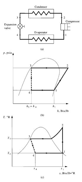
FIGURE 9.5 Single-stage ideal vapour compression cycle: (a)
schematic diagram; (b) p-h diagram; (c) T-s diagram.
9.24 CHAPTER NINE
For isentropic compression between points 1 and 2, applying the steady flow energy equation and
ignoring the change of kinetic energy, we have
h1 + 0 = h2 + W
-W = h2 – h1
Work input to the compressor Win, Btu / lb (kJ / kg), is given as
Win = h2– h1 (9.13)
Similarly, for condensation between points 2 and 3,
h2+ q#= h3+ 0
The heat released by the refrigerant in the condenser- q#, Btu / lb (kJ / kg), is
-q#= h2– h3 (9.14)
For the throttling process between points 3 and 4, assuming that the heat loss is negligible
h3+ 0 = h4 + 0
or h3= h4 (9.15)
The COPref of the single-stage ideal vapour compression cycle is
COPref = Refrigeration Effect/Work Input = (h1 – h4) / (h2 – h1) (9.16)
The mass flow rate of refrigerant, lb/h (kg/ s), flowing through the evaporator is
mr = Qrc / qrf (9.17)
where Qrc refrigerating capacity, Btu /h (W). From Eq. (9.16), the smaller the difference between
the condensing and evaporating pressures, or between condensing and evaporating temperatures,
the lower the Win input to the compressor at a specific Qrc and, therefore, the higher the COP.
A higher evaporating pressure pev and evaporating temperature Tev or a lower condensing pressure
pcon and condensing temperature Tcon will always conserve energy
Determination of Enthalpy by Polynomials
During the performance analysis of a refrigeration cycle, the enthalpies h of the refrigerant at
various points must be determined in order to calculate the refrigeration effect, work input, and
COP. The enthalpy of refrigerant at saturated liquid and saturated vapour state is a function of
saturated temperature or pressure. In other words, saturated temperature Ts and saturated pressure
pss of the refrigerant are dependent upon each other. Therefore, it is more convenient to evaluate
the enthalpy of refrigerant in terms of saturated temperature Ts within a certain temperature
range
h = ƒ (Ts) (9.18)
REFRIGERANTS, REFRIGERATION CYCLES, AND REFRIGERATION SYSTEMS 9.25
The enthalpy differential along the constant-entropy line within a narrower temperature range can
be calculated as
h2– h1= F(Ts2– Ts1) (9.19)
where h1, h2= enthalpy of refrigerant on constant-entropy line at points 1 and 2, Btu/ lb (kJ /kg)
Ts1, Ts2= temperature of saturated refrigerant at points 1and 2,°F (°C)
From the refrigerant tables published by ASHRAE, the following polynomial can be used to calculate
the enthalpy of saturated liquid refrigerant hlr, Btu / lb (kJ / kg), from its temperature Ts1 at a saturated
temperature from 20 to 120°F (- 7 to 50°C) with acceptable accuracy:
hlr= a1 + a2Ts1+ a3T2s1+ a4T3s1 (9.20)
where a1, a2, a3, a4= coefficients. For HCFC-22,
a1= 10.409 a2= 0.26851 a3 = 0.00014794 a4= 5.3429 X 10⁻⁷
Similarly, the polynomial that determines the enthalpy of saturated vapour refrigerant hvr, Btu / lb
(kJ/ kg), from its temperature Tsv in the same temperature range is
hvr = b1 + b2Tsv + b3T2sv + b4T3sv (9.21)
whereb1, b2, b3, b4 _ coefficients. For HCFC-22,
b1 = 104.465 b2 = 0.098445 b3 =-0.0001226 b4 =-9.861 X 10⁻⁷
The polynomial that determines the enthalpy changes of refrigerant along the constant-entropy line
for an isentropic compression process between initial state 1 and final state 2 is
h2–h1c1 _ c2(Ts2 _ Ts1) _ c3(Ts2 _ Ts1)2 _ c4(Ts2 _ Ts1)3 (9.22)
where c1, c2, c3, c4= coefficients
Ts1, Ts2= saturated temperature of vapour refrigerant corresponding to its pressure at initial
state 1 and final state 2,°F (°C)
For HCFC-22 within a saturated temperature range of 20 to 100°F:
c1 =-0.18165 c2=+0.21502 c3=-0.0012405 c4=+8.198 X 10⁻⁶
Computer programs are available that calculate the coefficients based on ASHRAE’s refrigerant tables
and charts.
Refrigeration Effect, Refrigerating Load, and Refrigerating Capacity
The refrigeration effect qrf, Btu / lb (J /kg or kJ/ kg), is the heat extracted by a unit mass of refrigerant
during the evaporating process in the evaporator. It can be calculated as
qrf=hlv –hen (9.23)
where hen, hlv= enthalpy of refrigerant entering and leaving evaporator, Btu / lb (J / kg). Refrigerating
load Qrl, Btu /h (W), is the required rate of heat extraction by the refrigerant in the evaporator. Itcan be calculated as
Qrl=m˙r(hlv–hen) (9.24)
wherem˙r= mass flow rate of refrigerant flowing through evaporator, lb/h (kg/ s).
Refrigerating capacity, or cooling capacity, Qrc, Btu /h (W), is the actual rate of heat extracted by
the refrigerant in the evaporator. In practice, the refrigeration capacity of the equipment selected is
often slightly higher than the refrigerating load. This is because the manufacturer’s specifications
are a series of fixed capacities. Occasionally, equipment can be selected so that its capacity is just
equal to the refrigeration load required. Refrigeration capacity Qrccan be calculated as
Qrc =m˙r(hrlv –hren) (9.25)
where hren, hrlv= enthalpy of refrigerant actually entering and leaving evaporator, Btu / lb (J /kg)
9.11 SUBCOOLING AND SUPERHEATING
Subcooling
Condensed liquid refrigerant is usually subcooled to a temperature lower than the saturated temperature
corresponding to the condensing pressure of the refrigerant, shown in Fig. 9.6a as point 3’.
This is done to increase the refrigerating effect. The degree of subcooling depends mainly on the
temperature of the coolant (e.g., atmospheric air, surface water, or well water) during condensation,
and the construction and capacity of the condenser.
The enthalpy of subcooled liquid refrigerant hsc, Btu / lb (J / kg), can be calculated as
hsc= hs,con –cpr(Ts,con –Tsc) (9.26)
where hs,con= enthalpy of saturated liquid refrigerant at condensing temperature, Btu/ lb (J /kg)
cpr= specific heat of liquid refrigerant at constant pressure, Btu/ lb ∙°F (J /kg∙°C)
Ts,con= saturated temperature of liquid refrigerant at condensing pressure,°F (°C)
Tsc= temperature of subcooled liquid refrigerant,°F (°C)
Enthalpy hscis also approximately equal to the enthalpy of the saturated liquid refrigerant at subcooled
temperature.
Superheating
As mentioned before, the purpose of superheating is to avoid compressor slugging damage. Superheating
is shown in Fig. 9.6b. The degree of superheat depends mainly on the type of refrigerant
feed and compressor as well as the construction of the evaporator. These are covered in detail in
Chap. 11.
Example 9.1. A 500-ton (1760-kW) single-stage centrifugal vapor compression system uses
HCFC-22 as refrigerant. The vapour refrigerant enters the compressor at dry saturated state. The
compression process is assumed to be isentropic. Hot gas is discharged to the condenser and
condensed at a temperature of 95°F (35°C). The saturated liquid refrigerant then flows through a
throttling device and evaporates at a temperature of 35°F (1.7°C). Calculate:
- The refrigeration effect
- The work input to the compressor
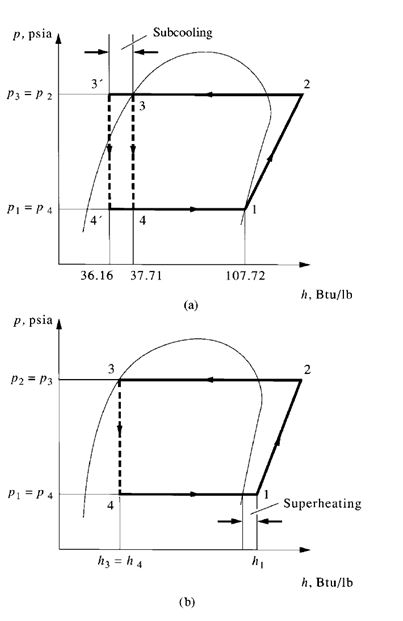
FIGURE 9.6 (a) Subcooling and (b) superheating.
- The coefficient of performance of this refrigeration cycle
- The mass flow rate of the refrigerant
Recalculate the COP and the energy saved in work input if the refrigerant is subcooled to a temperature
of 90°F (32.2°C).
Solution
- From Eq. (9.20), the enthalpy of the saturated liquid refrigerant at a temperature of 95°F (35°C),
point 3 as shown in Fig. 9.5a, is
h3=h4= 10.409 + 0.26851Ts+ 0.0001479T s2 + 5.3429 X 10⁻⁷T s3
= 10.409 + 0.26851(95) + 0.0001479(95)2+ 5.3429 X 10⁻⁷(95)3
= 10.409 + 25.508 + 1.335 + 0.458 = 37.71 Btu / lb
From Eq. (9.21), the enthalpy of saturated vapour refrigerant at a temperature of 35°F (1.7°C),
point 1, is
h1 = 104.465 + 0.098445Ts – 0.0001226T s2– 9.861 X 10⁻⁷T s3
= 104.47 + 0.098445(35) – 0.0001226(35)2– 9.861 X 10⁻⁷(35)3
= 104.47 + 3.445 – 0.150 – 0.042 = 107.72 Btu / lb
Then the refrigeration effect is calculated as
qrf=h1–h4= 107.72 – 37.71 = 70.01 Btu/ lb (162.8 kJ /kg)
- From Eq. (9.22), the enthalpy differential h2 _ h1 on the constant-entropy line corresponding to
a saturated temperature differential Ts2–Ts1 = 95 – 35 = 60°F in the two-phase region is
h2–h1=-0.18165 + 0.21502(Ts2–Ts1) – 0.0012405(Ts2–Ts1)2+ 8.1982 X 10⁻⁶(Ts2 _ Ts1)3
=- 0.18165 + 0.21502(60) – 0.0012405(60)2+ 8.1982 X 10⁻⁶(60)3
=-0.182 + 12.901 – 4.466 +1.771 = 10.02 Btu / lb
That is, the work input Win= h2–h1 = 10.024 Btu/ lb (23.73 kJ / kg).
- According to Eq. (9.16), COPref of the refrigerating system is calculated as
COPref = qrf/Win = 70.01/10.024 = 6.98
- From Eq. (9.17), the mass flow rate of the refrigerant can be calculated as
m˙ r= Qrc/ qrf = 500 X 12,000 / 70.01 = 85,702 lb / h (38,874 kg / h)
If the liquid refrigerant is subcooled to a temperature of 90°F, (32.2°C), then
h3=h4= 10.409 + 0.26851(90) + 0.0001479(90)2+ 5.3429 X 10⁻⁷(90)3
= 10.409 + 24.166 + 1.198 + 0.389 = 36.16 Btu/ lb
Refrigeration effect is then increased to
qrf = 107.72 – 36.16 = 71.56 Btu/ lb (166 kJ/kg)
Also COPref is increased to
COPref= 71.56 / 10.024 = 7.14
Since 1 ton = 200 Btu/min and 1 hp = 42.41 Btu/min, electric power input to the compressor Pin
without subcooling is
Pin= (500 X 200) / (42.41 X 6.98) = 337.8 hp (252 kW)
With subcooling,
Pin, s = (500 X 200) / (42.41 X 7.14) = 330.2 hp (246 kW)
Savings in electric energy are calculated as
(337.8 – 330.2) / 337.8 = 0.022, or 2.2%
9.12 MULTISTAGE VAPOR COMPRESSION SYSTEMS
When a refrigeration system uses more than single-stage compression process, it is called a multistage
system (as shown in Fig. 9.7), and may include the following:
- A high-stage compressor and a low-stage compressor
- Several compressors connected in series
- Two or more impellers connected internally in series and driven by the same motor or prime
mover, as shown in Fig. 9.7
- A combination of two separate refrigeration systems
The discharge pressure of the low-stage compressor, which is equal to the suction pressure of the
high-stage compressor, is called the interstage pressure.
The reasons for using a multistage vapour compression system instead of a single-stage system
are as follows:
- The compression ratio Rcom of each stage in a multistage system is smaller than that in a singlestage
unit, so compressor efficiency is increased. Compression ratio Rcom is defined as the ratio
of the compressor’s discharge pressure pdis, psia (kPa abs.), to the suction pressure at the compressor’s
inlet psuc, psia (kPa abs.), or
Rcom = pdis / psuc (9.27)
- Liquid refrigerant enters the evaporator at a lower enthalpy and increases the refrigeration effect.
- Discharge gas from the low-stage compressor can be desuperheated at the interstage pressure.
This results in a lower discharge temperature from the high-stage compressor than would be
produced by a single-stage system at the same pressure differential between condensing and
evaporating pressures.
- Two or three compressors in a multistage system provide much greater flexibility to accommodate
the variation of refrigeration loads at various evaporating temperatures during part-load operation.
The drawbacks of the multistage system are higher initial cost and a more complicated system
than that for a single-stage system.
Compound Systems
Multistage vapour compression systems are classified as compound systems or cascade systems.
Cascade systems are discussed in a later section.
A compound system consists of two or more compression stages connected in series. For
reciprocating, scroll, or screw compressors, each compression stage usually requires a separate
compressor. In multistage centrifugal compressors, two or more stages may be internally compounded
by means of several impellers connected in series.
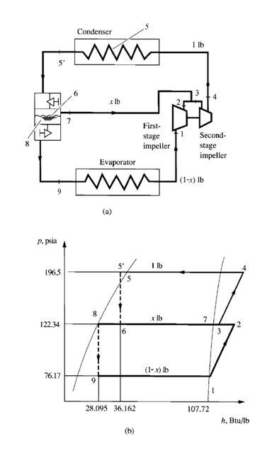
FIGURE 9.7 Two-stage compound system with a flash cooler: (a)
schematic diagram; (b) refrigeration cycle.
Interstage Pressure
Interstage pressure is usually set so that the compression ratio at each stage is nearly the same for
higher COPs. For a two-stage compound system, interstage pressure pi, psia (kPa abs.), can be
calculated as
(9.28)
where pcon= condensing pressure, psia (kPa abs.)
pev= evaporating pressure, psia (kPa abs.)
For a multistage vapour compression system with z stages, the compression ratio Rcom for each stage
can be calculated as
(9.29)
Flash Cooler and Intercooler
In compound systems, flash coolers are used to subcool liquid refrigerant to the saturated temperature
corresponding to the interstage pressure by vaporizing part of the liquid refrigerant. Intercoolers
are used to desuperheat the discharge gas from the low-stage compressor and, more often, to
subcool also the liquid refrigerant before it enters the evaporator.
9.13 TWO-STAGE COMPOUND SYSTEM WITH
A FLASH COOLER
Flow Processes
Figure 9.7a is a schematic diagram of a two-stage compound system with a flash cooler, and Fig. 9.7b
shows the refrigeration cycle of this system. Vapour refrigerant at point 1 enters the first-stage impeller
of the centrifugal compressor at the dry saturated state. It is compressed to the interstage pressure pi at
point 2 and mixes with evaporated vapour refrigerant from the flash cooler, often called an economizer.
The mixture then enters the second-stage impeller at point 3. Hot gas, compressed to condensing pressure
pcon, leaves the second-stage impeller at point 4. It is then discharged to the condenser, in which
the hot gas is desuperheated, condensed, and often subcooled to liquid state at point 5_. After the condensing
process, the subcooled liquid refrigerant flows through a throttling device, such as a float
valve, at the high-pressure side. A small portion of the liquid refrigerant flashes into vapour in the flash
cooler at point 7, and this latent heat of vaporization cools the remaining liquid refrigerant to the
saturation temperature corresponding to the interstage pressure at point 8. Inside the flash cooler, the
mixture of vapour and liquid refrigerant is at point 6. Liquid refrigerant then flows through another
throttling device, a small portion is flashed at point 9, and the liquid-vapour mixture enters the evaporator.
The remaining liquid refrigerant is vaporized at point 1 in the evaporator. The vapour then flows to
the inlet of the first-stage impeller of the centrifugal compressor and completes the cycle.
Fraction of Evaporated Refrigerant in Flash Cooler
In the flash cooler, out of 1 lb of refrigerant flowing through the condenser, x lb of it cools down the
remaining portion of liquid refrigerant (1 –x) lb to saturated temperature T8 at interstage pressure
- pi. Because h5‘ is the enthalpy of the subcooled liquid refrigerant entering the flash cooler, h6 is the
enthalpy of the mixture of vapour and liquid refrigerant after the throttling device, for a throttling
process, h5‘=h6. Enthalpies h7 and h8 are the enthalpies of the saturated vapour and saturated
liquid, respectively, at the interstage pressure, and h9 is the enthalpy of the mixture of vapour and
liquid refrigerant leaving the flash cooler after the low-pressure side throttling device. Again, for a
throttling process, h8=h9.
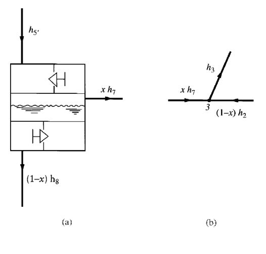
FIGURE 9.8 Heat balance of entering and leaving refrigerants in a
flash cooler and at the mixing point: (a) in the flash cooler; (b) at the
mixing point 3 before entering the second-stage impeller
If the heat loss from the insulated flash cooler to the ambient air is small, it can be ignored. Heat
balance of the refrigerants entering and leaving the flash cooler, as shown in Fig. 9.8a, gives
Sum of heat energy of refrigerant entering flash cooler
= Sum of heat energy of refrigerant leaving flash cooler
that is,
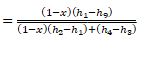
h5′ =xh7+ (1 –x)h8
The fraction of liquid refrigerant evaporated in the flash cooler x is given as
(9.30)
The fraction x also indicates the quality, or dryness fraction, of the vapour and liquid mixture in the
flash cooler at the interstage pressure.
Enthalpy of Vapour Mixture Entering Second-Stage Impeller
Ignoring the heat loss from mixing point 3 to the surroundings, we see that the mixing of the
gaseous refrigerant discharged from the first-stage impeller at point 2 and the vaporized refrigerant
from the flash cooler at point 7 is an adiabatic process. The heat balance at the mixing point before
the second-stage impeller, as shown in Fig. 9.7b, is given as
h3= (1 –x)h2+xh7 (9.31)
where
h2= enthalpy of gaseous refrigerant discharged from first-stage impeller, Btu/ lb (kJ /kg)
h3= enthalpy of mixture at point 3, Btu/ lb (kJ /kg)
h7= enthalpy of saturated vapor refrigerant from flash cooler at point 7, Btu/ lb (kJ /kg)
COPref= qrf / Win
Coefficient of Performance
For 1 lb (kg) of refrigerant flowing through the condenser, the amount of refrigerant flowing
through the evaporator is (1 – x) lb (kg). The refrigeration effect qrfper lb (kg) of refrigerant flowing
through the condenser, Btu / lb, (kJ/ kg), can be expressed as
qrf= (1 – x)(h1 – h9) (9.32)
where
h1 = enthalpy of saturated vapour leaving evaporator, Btu / lb (kJ /kg)
h9 = enthalpy of refrigerant entering evaporator, Btu / lb (kJ /kg)
Total work input to the compressor (including the first- and second-stage impeller) Win per lb (kg)
of refrigerant flowing through the condenser, Btu / lb (kJ / kg), is
Win = (1 – x)(h2 – h1) + h4 – h3 (9.33)
where h4 = enthalpy of the hot gas discharged from the second-stage impeller, Btu/ lb (kJ / kg). The
coefficient of performance of the two-stage compound system with a flash cooler COPref is
_
 (9.34)
The mass flow rate of refrigerant at the condenser r, lb/h (kg/ s), is
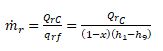 (9.35)
where Qrc = refrigeration capacity, Btu /h (W).
In a two-stage compound system with a flash cooler, a portion of the liquid refrigerant is flashed
into vapour going directly to the second-stage suction inlet, so less refrigerant is compressed in
the first-stage impeller. Furthermore, the remaining liquid refrigerant is cooled to the saturated
temperature corresponding to the interstage pressure, which is far lower than the subcooled liquid
temperature in a single-stage system. The increase in refrigeration effect and the drop in compression
work input lead to a higher COPref than in a single-stage system.
Although the initial cost of a two-stage compound system is higher than that for a single-stage
system, the two-stage compound system with a flash cooler is widely used in large central hydronic
air conditioning systems because of the high COPref.
Example 9.2. For the same 500-ton (1758-kW) centrifugal vapour compression system as in
Example 9.1, a two-stage compound system with a flash cooler is used instead of a single-stage
centrifugal compressor. Vapor refrigerant enters the first-stage impeller at a dry saturated state, and
the subcooled liquid refrigerant leaves the condenser at a temperature of 90°F (32.2°C). Both
compression processes at the first-stage impeller and the second-stage impeller are assumed to be
isentropic. Evaporating pressure is 76.17 psia (525kPa abs.), and the condensing pressure is 196.5
psia (1355 kPa abs.). Other conditions remain the same as in Example 9.1. Calculate
- The fraction of liquid refrigerant vaporized in the flash cooler
- The refrigeration effect per lb (kg) of refrigerant flowing through the condenser
- The total work input to the compressor
- The coefficient of performance of this refrigerating system
- The mass flow rate of refrigerant flowing through the condenser
- The percentage of saving in energy consumption compared with the single-stage vapor compression
System
Solution
- Based on the data calculated in Example 9.1, enthalpy of vapour refrigerant entering the firststage
impeller h1= 107.72 Btu/lb and the enthalpy of the subcooled liquid refrigerant leaving
the condenser h5′= 36.162 Btu/ lb, as shown in Fig. 9.6b. From Eq. (9.28) and the given data,
the interstage pressure can be calculated as

From the Table of Properties of Saturated Liquid and Vapour for HCFC-22 in ASHRAE Handbook
1989, Fundamentals, for pi= 122.34 psia, the corresponding interstage saturated temperature Tiin
the two-phase region is 63.17°F.
From Eq. (9.20), the enthalpy of liquid refrigerant at saturated temperature 63.17°F is
h8=h9= 10.409 + 0.26851(63.17) + 0.00014794(63.17)2+ 5.3429(63.17)3
= 10.409 + 16.961 + 0.59 + 0.135 = 28.095 Btu/ lb
Also, from Eq. (9.21), the enthalpy of the saturated vapour refrigerant at a temperature of 63.17°F is
h7 = 104.465 + 0.098445(63.17) – 0.0001226(63.17)2– 9.861 X 10⁻⁷(63.17)3
= 104.465 + 6.219 – 0.489 – 0.249 = 109.946 Btu/ lb
Then, from Eq. (9.30), the fraction of vaporized refrigerant in the flash cooler is
X = (h5 – h8) / (h7 – h8)
= (36.162 – 28.095) / (109.946 – 28.095) = 0.09856
- From Eq. (9.32), the refrigeration effect is
qrf = (1 –x)(h1–h9) = (1 – 0.09856)(107.72 – 28.095)
= 71.78 Btu/ lb (167 kJ/kg)
From Eq. (9.22), the enthalpy differential h2–h1 corresponding to a saturated temperature differential
Ts2 –Ts1= 63.17 – 35 = 28.17°F in the two-phase region is
h2 –h1=-0.18165 + 0.21502(28.17) – 0.0012405(28.17)2+ 8.1982 – 10X 6(28.17)3
=-0.182 + 6.057 – 0.984 + 0.183 = 5.074 Btu/ lb
Similarly, from Eq. (9.22), the enthalpy differential h4–h3 corresponding to a saturated temperature
differential Ts–Ti= 95 – 63.17 = 31.83°F is
h4 –h3=-0.020 + 0.16352(31.83) – 0.00035106(31.83)2+ 1.9177 X 10⁻⁶(31.83)3
=-0.020 + 5.205 – 0.356 + 0.062 = 4.891 Btu/ lb
Then, from Eq. (9.33), the total work input to the compressor is calculated as
Win= (1 –x)(h2–h1) +h4–h3
= (1 – 0.09856)(5.074) + 4.891 = 9.465 Btu/ lb (22.0 kJ /kg)
- The coefficient of performance of this two-stage compound system is
COPref = (qrf / win) = (71.78 / 9.465) = 7.58
The mass flow rate of refrigerant flowing through the condenser can be evaluated as
rc / qrf = 500*12000 / 71.78 = 83,588 lb / h (37,916 kg / h)
- From the results in Example 9.1, the power input to the single-stage system is 330.2 hp. The
power input to the two-stage compound system is
Pin = (500*200) / (42.41*7.58) = 311.1 hp (232 kW)
Energy saving compared with the single-stage system is calculated as
= (330.2 – 311.1) / 330.2 = 0.058, or 5.8%
9.14 THREE-STAGE COMPOUND SYSTEM WITH
A TWO-STAGE FLASH COOLER
To reduce the energy consumption of refrigeration systems in air conditioning, the three-stage compound
system with a two-stage flash cooler became a standard product in the 1980s. Fig. 9.9 shows
the schematic diagram and refrigeration cycle of this system.
Flow Processes
In Fig. 9.9, vapour refrigerant enters the first-stage impeller of the centrifugal compressor at a dry
saturated state, point 1. After the first-stage compression process, at point 2, it mixes with the vaporized
refrigerant coming from the low-pressure flash cooler at point 12. At point 3, the mixture
enters the second-stage impeller. After the second-stage compression process at point 4, it mixes
again with vaporized refrigerant from the high-pressure flash cooler at point 9. The mixture, at
point 5, is then compressed to the condensing pressure in the third-stage impeller. At point 6, the
hot gas enters the condenser, condenses to liquid, and subcools to a temperature below the condensing
temperature. Subcooled liquid refrigerant leaves the condenser at point 7’ and flows through a
two-stage flash cooler and the associated throttling devices, in which a small portion of liquid refrigerant
is successively flashed into vapour at interstage pressure pi1, point 9, and interstage pressure
pi2, point 12. The liquid-vapour mixture enters the evaporator at point 14, and the remaining liquid
refrigerant evaporates into vapour completely in the evaporator.
Fraction of Refrigerant Vaporised in Flash Cooler
Based on the heat balance of the refrigerants entering and leaving the high-pressure flash cooler, as
shown in Fig. 9.10a, the fraction of liquid refrigerant vaporised in the high-pressure flash cooler
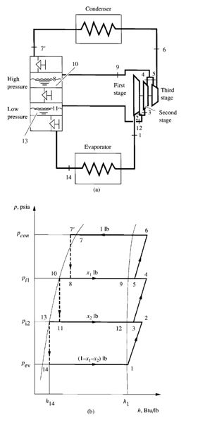
FIGURE 9.9 Three-stage compound system with a two-stage flash
cooler: (a) schematic diagram; (b) refrigeration cycle.
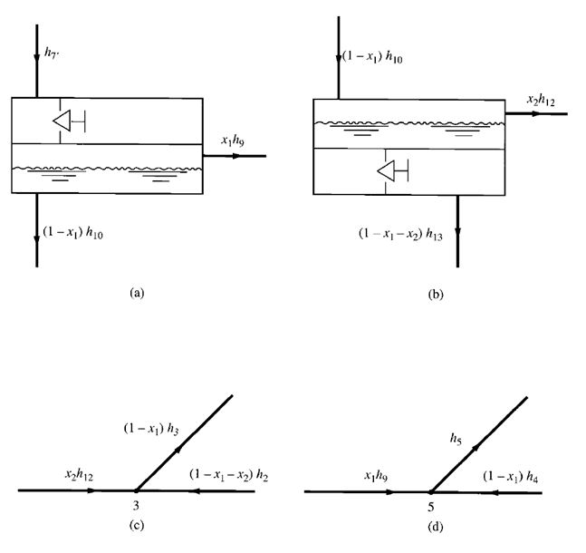
FIGURE 9.10 Heat balance of refrigerants entering and leaving the high-pressure and low-pressure flash
cooler and mixing points. (a) High-pressure flash cooler; (b) low-pressure flash cooler; (c) at the mixing point
before entering second-stage impeller; (d) at the mixing point before entering third-stage impeller.
x1 at interstage pressure pi1 can be calculated as
h7’= (1 –x1)h10+x1h9
Therefore,
X1 = (h7’– h10) / (h9 – h10) (9.36)
where h7’, h9, h10= enthalpies of refrigerants at points 7’ 9, and 10, respectively, Btu / lb (kJ / kg).
In the same manner, the heat balance of the refrigerant entering and leaving the low-pressure flash
cooler, as shown in Fig. 9.10b, may be expressed as
(1 – x1)h10 = x2h12 + (1 – x1 – x2)h13
where h12, h13 _ enthalpies of the refrigerant at points 12, and 13, respectively, Btu / lb (kJ / kg). The
fraction of liquid refrigerant vaporized in the low-pressure flash cooler x2 at an interstage pressure
pi2 can be evaluated as
x2 = (1 – x1) (h10 – h13) / h12 – h13 (9.37)
Coefficient of Performance of Three-Stage System
From a heat balance of the refrigerants entering and leaving the mixing point before the inlet of the
second-stage impeller, as shown in Fig. 9.9c, the enthalpy of the mixture at point 3, h3 (Btu/ lb or
kJ/ kg) is given as
h3 = (1 –x1–x2)h2+x2h12/ 1 – x1 (9.38)
where h2= enthalpy of the gaseous refrigerant discharged from the first-stage impeller at point 2,
Btu/ lb (kJ / kg). As shown in Fig. 9.9d, the enthalpy of the mixture of vapour refrigerants at point 5,
h5, Btu / lb (kJ / kg), can also be evaluated as
h5= (1 –x1)h4+x1h9 (9.39)
where h4= enthalpy of the gaseous refrigerant discharged from the second-stage impeller at point
4, Btu/ lb (kJ / kg). The refrigeration effect qrfin Btu/ lb of refrigerant flowing through the condenser
is given as
qrf = (1 –x1–x2)(h1–h14) (9.40)
where h1, h14= enthalpies of the refrigerants leaving the evaporator at point 1 and entering the
evaporator at point 14, respectively, Btu / lb (kJ / kg). Total work input to the three-stage compressor
Win, Btu / lb (kJ / kg) of refrigerant flowing through the condenser, is given by
Win= (1 –x1–x2)(h2–h1) + (1 –x1)(h4–h3) +h6–h5 (9.41)
where h6 _ enthalpy of the hot gas discharged from the third-stage impeller at point 6, Btu/ lb
(kJ/ kg).
From Eqs. (9.40) and (9.41), the coefficient of performance of this three-stage system with a
two-stage flash cooler is
COPref = qrf / Win = (1 –x1–x2)(h1–h14) / (1 – x1 – x2)(h2 – h1) + (1 – x1)(h4 – h3) + (h6 – h5) (9.42)
A three-stage compound system with a two-stage flash cooler often has a further energy saving of
about 2 to 5 percent compared to a two-stage compound system with a flash cooler.
The mass flow rate of the refrigerant flowing through the condenser ṁr, lb/ h (kg/h), can be calculated
As
ṁr = Qrc / qrf = qrc / (1 – x1 – x2)(h1 – h14) (9.43)
9.15 TWO-STAGE COMPOUND SYSTEM WITH
A VERTICAL INTERCOOLER
When an evaporating temperature in the range of -10 to -50°F (-23.3 to -45.6°C) is required, a
two-stage compound system using reciprocating or screw compressors is usually applied. Figure 9.11
shows the schematic diagram and the refrigeration cycle of a two-stage compound system with a vertical
coil intercooler. The subcooled liquid refrigerant from the receiver at point 5_ is divided into two
streams. One stream enters the coil inside the intercooler. The other stream enters its shell after throttling
to point 6, the interstage pressure.
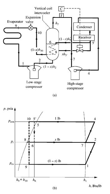
FIGURE 9.11 Two-stage compound system with a vertical coil intercooler:
- (a) schematic diagram; (b) refrigeration cycle.
In the intercooler shell, some of the liquid refrigerant vaporizes to saturated vapour at point 7,
drawing latent heat from the liquid in the coil at point 5
, further subcooling it to point 10. This subcooled
liquid is throttled by the expansion valve at point 10 and then evaporates to saturated vapour
at point 1 in the evaporator. Vapour refrigerant from the evaporator at point 1 enters the low-stage
compressor. The compressed hot gas at point 2 discharges into the intercooler, mixing with the
liquid from the receiver at the interstage pressure. The liquid level in the intercooler is controlled by
the saturated temperature at the interstage pressure in the intercooler. The saturated vapour from
the vertical coil intercooler at point 7 enters the high-stage compressor. At point 4, hot gas is
discharged from the high-stage compressor and then condensed and subcooled to point 5’ in the
condenser.
In this system, x is the fraction of liquid refrigerant vaporized in the intercooler, and h10 is the
enthalpy of the liquid refrigerant that has been subcooled in the vertical coil. Based on the heat balance
of the refrigerants entering and leaving the intercooler, as shown in Fig. 9.11a,
(1 –x)h5’+xh5+ (1 –x)h2=h7+ (1 –x)h10
Then
X = h2 –h7+h5’–h10/ h2–h10 (9.44)
This type of system is often used in low-temperature refrigerated cold storage and other industrial
applications. Ammonia is often used as the refrigerant.
Comparison between Flash Cooler and Vertical Coil Intercooler
Hot gas discharged from the low-stage compressor is always desuperheated to a nearly saturated vapor
state at the interstage pressure in the vertical coil intercooler. This process is more appropriate
for a refrigerant like ammonia, which has a high discharge temperature. In flash coolers, desuperheating
is caused by the mixing of flashed vapour and hot gas, and will not result in a dry saturated
state. Therefore, flash coolers are usually used in refrigeration systems using HCFCs or HFCs.
The liquid refrigerant flowing inside the coils of a vertical coil can be maintained at a slightly
lower pressure than condensing pressure, whereas the pressure of liquid refrigerant in the flash
cooler is decreased to the interstage pressure. Some refrigerant may be preflashed before the throttling
device, causing a waste of refrigerating capacity. For a flash cooler, the available pressure drop
in the throttling device is lower.
9.16 CASCADE SYSTEMS
A cascade system consists of two separate single-stage refrigeration systems: a lower system that
can better maintain lower evaporating temperatures and a higher system that performs better at
higher evaporating temperatures. These two systems are connected by a cascade condenser in
which the condenser of the lower system becomes the evaporator of the higher system as the higher
system’s evaporator takes on the heat released from the lower system’s condenser.
It is often desirable to have a heat exchanger between the liquid refrigerant from the cascade
condenser and the vapor refrigerant leaving the evaporator of the lower system. The liquid refrigerant
can be subcooled to a lower temperature before entering the evaporator of the lower system, as
shown in Fig. 9.12a. Because the evaporating temperature is low, there is no danger of too high a
discharge temperature after the compression process of the lower system.
When a cascade system is shut down while the temperature of the ambient air is 80°F (26.7°C),
the saturated vapor pressure of the refrigerant increases. For a lower system using HFC-125 as the
refrigerant, this saturated pressure may increase to 208.91 psia (1440 kPa abs.). For safety reasons, a
relief valve at the cascade condenser connects to an expansion tank, designed to store the refrigerant
from the lower system in case of shutdown. For extremely low evaporating temperatures, a multistage
compression system may be used in either the lower or higher system of a cascade system.
Advantages and Disadvantages
The main advantage of a cascade system is that different refrigerants, equipment, and oils can
be used for the higher and the lower systems. This is especially helpful when the evaporating
temperature required in the lower system is less than -100°F (-73°C). The specific volume of the
suction vapour vsuc is extremely important in such temperature applications. A greater vsuc always requires
a large compressor and more space. For instance, at -80°F (-62.2°C), saturated vapour of
HCFC-22 has a vsuc of 9.70 ft3 / lb (0.605 m3 / kg), whereas for HFC-125 vsuc is only 4.67 ft3 / lb
(0.291 m3 / kg).
One disadvantage of a cascade system is the overlap of the condensing temperature of the lower
system and the evaporating temperature of the higher system for heat transfer in the condenser. The
overlap results in higher energy consumption. Also a cascade system is more complicated than a
compound system.
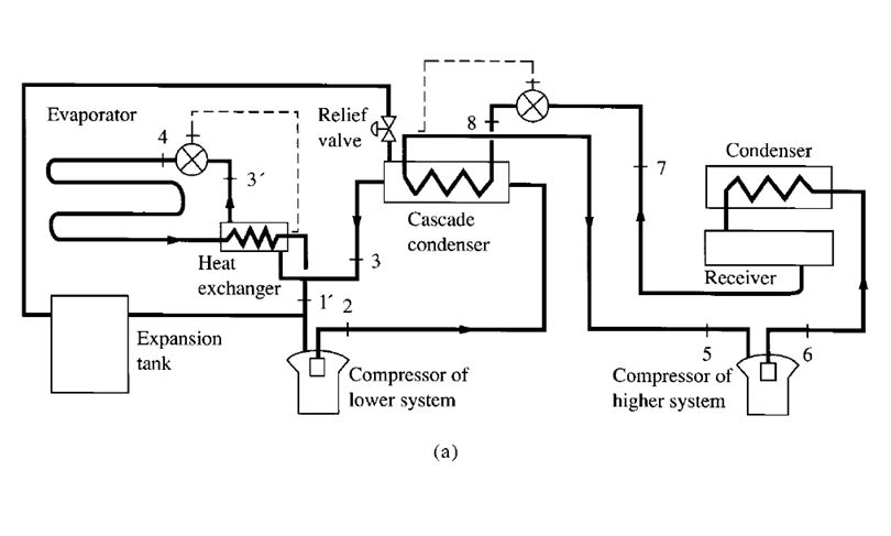
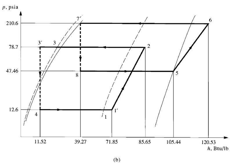
FIGURE 9.12 Cascade system: (a) schematic diagram; (b) p–h diagram; (c) T–s diagram.
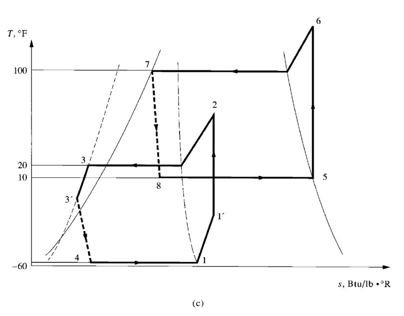
FIGURE 9.12 (Continued)
Performance of Cascade System
The performance of the cascade system can be measured in terms of 1 lb (kg) of refrigerant in the
lower system, for the sake of convenience. In Fig. 9.12b and c, which shows the refrigeration cycles
on p–h and T–s diagrams, the lower system is indicated by points 1, 2, 3’, and 4, and the higher system
by points 5, 6, 7, and 8. The desired low-temperature refrigeration effect of the cascade system
can be calculated as
qrf=h1–h4 (9.45)
If the heat transfer between the cascade condenser and the surroundings is ignored, then the heat released
by the condenser of the lower system ṁl(h2–h3)is equal to the refrigerating load on the
evaporator of the higher system ṁh(h5 –h8), that is
ṁl(h2 – h3) = ṁh(h5 – h8)
where ṁl,ṁh=mass flow rate of refrigerants in lower and higher systems respectively, lb/h
(kg/ s). Therefore, the ratio of the mass flow rate of refrigerant in the higher system to the mass flow
rate in the lower system is
ṁl /ṁh= h2– h3 / h5– h8 (9.46)
The mass flow rate of refrigerant in the lower systemṁl, lb/h (kg/ s), is
ṁl= qrc,l / qrf,l (9.47)
where qrc,l = refrigeration capacity of lower system, Btu/h (W)
qrf,l = refrigeration effect of lower system, Btu/ lb (J / kg)
Total work input to the compressors in both higher and lower systems Win, Btu / lb (J / kg), of refrigerant
in the lower system can be evaluated as
Win= (h2–h1’) +ṁh(h6–h5) / ṁl (9.48)
where h1’= enthalpy of vapour refrigerant leaving heat exchanger, Btu/ lb (J/kg). The coefficient of
performance of the cascade system is given as
COPref = qrf / Win = ṁl(h1– h4) / ṁl(h2– h1’) +ṁh(h6– h5) (9.49)
Example 9.3. A cascade system for an environmental chamber is designed to operate at the following
conditions during summer:
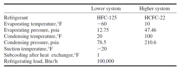
Vapour refrigerant enters the compressor of the higher system at a dry saturated state, and liquid refrigerant
leaves the condenser of the higher system without subcooling. Ignore the pressure losses
in the pipelines and valves, and assume that the compression processes for both the higher and
lower systems are isentropic.
Based on the data from the Properties of Saturated Liquid and Saturated Vapour of HFC-125
listed in ASHRAE Handbook 1997, Fundamentals, the following formulas can be used to calculate
the enthalpies of the refrigerants:
Enthalpy of refrigerant HFC-125 at saturated liquid state at temperature Tslbetween 0 and 50°F
(_17.8 and 10°C) hsl, Btu / lb (kJ / kg), is
hsl = 11.04 + 0.300Tsl
Enthalpy of refrigerant HFC-125 at saturated vapour state at temperature Tsvbetween -80 and
-30°F ( -62.2 and -34.4°C) hsv, Btu / lb (kJ / kg), is
hsv= 63.30 + 0.14[Tsv-(-80)]
Enthalpy difference of vapour refrigerant HFC-125 along the constant-entropy line when Tcon<
30°F (-1.1°C) and Tev> 80°F (26.7°C) is
∆hsv = 0.175(Tcon–Tev)
Here Tcon represents the condensing temperature and Tev the evaporating temperature, both in
°F (°C). The specific heat of saturated vapour of HFC-125 cpv, in the temperature range of -80 to
-40°F (-62.2 to -40°C) is 0.14 Btu/ lb ·°F (586 J/kg·°C). The specific heat of saturated liquid
of HFC-125 cplin the temperature range of 0 to 50°F (-17.8 to 10°C) is 0.300 Btu/ lb ·°F (1256
J/kg·°C).
Calculate:
- The refrigeration effect per pound (kilogram) of refrigerant in the lower system
- Total work input to the compressors
- Coefficient of performance of this cascade system
- Mass flow rates of the refrigerants in the higher and lower systemsSolution
- From the given values, the enthalpy of the saturated vapour refrigerant at -60°F is
h1=63.30 +0.14[Tsv -(-80)]
=63.30 +0.14[ -60 -(-80)] =66.10 Btu/ lb
Enthalpy of saturated liquid refrigerant at a condensing temperature of 20°F is
h3= 11.04 + 0.30Tsl
= 11.04 + 0.30(20) = 17.04 Btu/ lb
and from Eq. (9.26)
h1’=h4=h3–cpl(T3–T3’)
= 17.04 – 0.30(20 – 1) = 11.34 Btu/ lb
Then the refrigeration effect of the lower system is
qrf,l=h1–h4= 66.12 – 11.34 = 54.78 Btu/ lb (127.4 kJ /kg)
- Enthalpy of superheated vapour refrigerant after the heat exchanger in the lower system is
h1’=h1+cpv(degree of superheat)
= 66.12 + 0.14[ -20 – (-60)] = 71.72 Btu/ lb
Enthalpy difference (h2 –h1’) along the constant-enthalpy line of the lower system is
h2–h1’= 0.175 (Tcon–Tlv)
= 71.72 + 14.0 = 85.72 Btu/ lb
From Eq. (9.20), the enthalpy of saturated vapour refrigerant HCFC-22 in the higher system is
h5= 104.465 + 0.098445Ts– 0.0001226Ts2– 9.861 x 10⁻⁷Ts3
= 104.465 + 0.098445(10) – 0.0001226(10)2 – 9.861 x 10⁻⁷(10)3
= 104.465 + 0.984 – 0.012 – 0.001 = 105.436 Btu/ lb
From Eq. (9.22), the enthalpy difference along the constant-entropy line of the higher system is
h6–h5=-0.18165 + 0.21502(Ts2–Ts1) – 0.0012405(Ts2–Ts1)2+ 8.1982 x 10 -6(Ts2–Ts1)3
=-0.18165 + 0.21502(100 – 10) – 0.0012405(100 – 10)2+ 8.1982 x 10⁻⁶(100 – 10)3
= 15.09 Btu/ lb
According to Eq. (9.20), the enthalpy of liquid refrigerant HCFC-22 at condensing temperature
100°F in the higher system is
h7=h8= 10.409 + 0.26851Ts+ 0.00014794 (T s2) + 5.3429 x 10⁻⁷T s3
= 10.409 + 0.26851(100) + 0.00014794(1002) + 5.3429 x 10⁻⁷(1003) = 39.27 Btu / lb
From Eq. (9.46), the ratio of the mass flow rate of refrigerant in the higher system to that of the
lower system is
ṁh / ṁl = h2 – h3 / h5 – h8 =85.72 – 17.04 / 105.44 – 39.27 = 1.04
Then, from Eq. (9.48), the total work input to the compressors is
Win= (h2–h1’) + ṁh(h6 – h5) / ṁl
= 14.0 + 1.04(15.09) = 29.69 Btu / lb (69.06 kJ / kg)
- Coefficient of performance of the cascade system is
COPref= qrf/ Win = 54.78 / 29.69 = 1.85
- Mass flow rate of refrigerant in the lower system is
ṁl = Qrc,l / qrf,l = 100000 / 54.78= 1825 lb / h (828 kg / h)
The mass flow rate of refrigerant in the higher system is
ṁh= 1.04 ṁl= 1.04(30.42) = 1898 lb / h (861 kg / h)
9.17 AIR EXPANSION REFRIGERATION CYCLES
Thermodynamic Principle
According to the steady flow energy equation
h1 + v12 / 2gc x 778 + q# = (h2 + v22)/ (2gc x 778) + W
For an adiabatic process, q#= 0. Assuming that the difference between the kinetic energy v12/(2gc)
and v22/(2gc) is small compared with the enthalpy difference h1–h2, it can be ignored. For air
expanding in a turbine and producing work, the above equation can be rewritten as
W = h1 – h2
Usually air can be considered a perfect gas, so
∆h =cp∆TR (9.50)
where cp= specific heat of air at constant pressure, Btu/ lb ·°R (kJ/kg·K)
TR= absolute temperature, °R (K)
And
W =cp(TR1–TR2) (9.51)
When the expansion process is a reversible adiabatic process, the temperature-pressure relationship
can be expressed as
TR1 / TR2 = (P1 / P2)(y-1)/y (9.52)
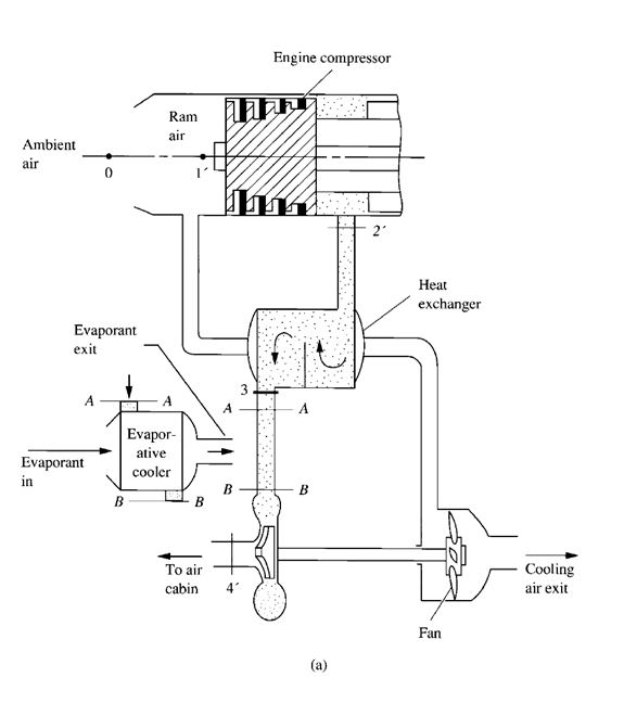
FIGURE 9.13 Air expansion refrigeration system and refrigeration cycle. (a) refrigeration system;
- air expansion refrigeration cycle.
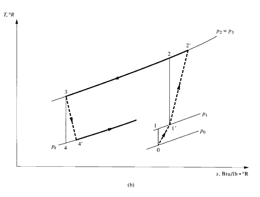
FIGURE 9.13 (Continued)
where p1, p2 _ air pressure at inlet and outlet of turbine, psia (kPa abs.)
_ ratio of specific heat at constant pressure to specific heat at constant volume
Equations (9.51) and (9.52) demonstrate that when air expands in a turbine and produces work, its
absolute temperature TR1 drops to TR2. The decrease in absolute temperature is proportional to the
pressure ratio (p1 /p2) (y-1) / yand the work produced W. The greater the pressure drop in the turbine,
the lower the temperature at the outlet of the turbine. This type of refrigeration has been used for air
conditioning systems in many aircraft.
Flow Processes of a Basic Air Expansion System for Aircraft
Figure 9.13a is a schematic diagram of a basic air expansion refrigerating system, and Fig. 9.13b
depicts the air expansion refrigeration cycle. In Fig. 9.13, ambient air that surrounds an aircraft
flying at subsonic speed and at high altitude, at point 0 with pressure p0, is rammed into the engine
scoop. Before entering the engine, the pressure of the air at point 1’ is increased to p1. When ram air
enters the engine compressor, it is compressed to pressure p2 and bleeds to a heat exchanger at point
2’. In the heat exchanger, the bleed air is cooled at constant pressure to point 3 by another stream of
ram air extracted by a fan. Bleed air is then expanded in a turbine and cooled to point 4’. This cold
air is supplied to the cabin and flight deck for air conditioning. Cabin air is then discharged to the
atmosphere after absorbing the sensible and latent heat from these conditioned spaces. Air expansion
refrigeration cycles for aircraft are open cycles because there is no recirculated air.
Another alternative is to add an evaporative cooler between section A–A and B–B, as shown in
Fig. 9.13, to cool the supply air a few degrees more. An evaporant such as water or alcohol can be
used to extract heat from the supply air by indirect contact.
The stream of ram air, extracted by a fan driven by the cooling turbine to cool the bleed air, is
also discharged to the atmosphere at the cooling air exit. The work output of the turbine is mainly
used to drive the fan.
Air Expansion Cycle
The air expansion refrigeration cycle is different from a vapour compression cycle because the refrigerant,
air, remains in gaseous form, does not evaporate, and condenses. Air is also not recirculated
and is used directly as the supply air for cooling the conditioned spaces.
Work input to the engine compressor Wc, Btu / lb (kJ / kg), is given by
Wc=cp(TR2’TR1’) (9.53)
where TR1’, TR2’= absolute temperature of ram air and air after compression process, respectively,
°R (K). The rate of heat transfer in the heat exchanger between the bleed air and the ambient air for
cooling Qex, Btu /h (W), can be calculated as
Qex=ṁbcp(TR2’–TR3) (9.54)
where TR3= absolute temperature of air after heat exchanger, °R (K)
ṁb= mass flow rate of bleed air, lb/h (kg/ s)
Work output from the turbine Woduring the expansion process, Btu/ lb (J / kg), can be calculated as
Wo _ cp(TR3 ‘ TR4’ ) (9.55)
where TR4’= absolute temperature of cold supply air at exit of turbine, °R (K). The amount of sensible
heat Qsen absorbed by the cold supply air in the air cabin or in the flight deck, Btu/h (W), is
Qsen=ṁbcp(TRr–TR4’ ) (9.56)
where TRr = absolute temperature of air cabin, °R (K). The relationship between temperature and
pressure for an isentropic compression process is
TR2’/ TR1= (P2 / P1)(y-1)/y (9.57)
For an isentropic expansion process, the relationship between temperature and pressure is
TR3/ TR4= (P3/ P4)(y-1)/y (9.58)
where TR2, TR4= absolute temperature of air after isentropic compression and isentropic expansion
processes, °R (K).
The isentropic efficiency for the compressor ɳcis
ɳc=cp(TR2–TR1’ ) / cp(TR2’–TR1’ ) (9.59)
Similarly, isentropic efficiency for the turbine ɳt is
ɳt = TR3 – TR4’ /TR3 – TR4 (9.60)
If ɳc, ɳt, TR1’ ,TR3, and pressure ratios p2 /p1 and p3 /p4 are known values, TR2 , and TR4 , can be determined
by using Eqs. (9.57) to (9.60).
The effectiveness of the heat exchanger ɛ can be evaluated as
ɛ = cpṁb(TR2’ – TR3) / cpṁb( TR2’ – TRt1) = (TR2’–TR3)/ (TR2’–TRt1) (9.61)
where TR2’, TR3= absolute temperature of bleed air entering and leaving heat exchanger, °R (K)
TRt1= absolute total temperature of cooling ram air entering heat exchanger,
measured at outer heat-transfer surface at rest, °R (K)
From Eq. (9.61), ɛ depends mainly on the construction of the heat exchanger and the ratio ṁb /ṁc, if
the difference of cpbetween bleed and cooling ram air is ignored. Here ṁcindicates the mass flow
rate of cooling ram air, lb/h (kg/ s).
If air at a velocity v with an absolute temperature TRfinally reaches a total temperature TRtwhen
brought to rest adiabatically, then, based on the steady flow energy equation;
cpTR = v2/ 2gcx 778 = cpTRt
or,
TRt=TR+ v2/ 2cp(778gc) (9.62)
When the air velocity v < 200 ft/ s (61 m/ s), the term v2 / [(2cp)(778gc)] is small compared with TR
and can be ignored. Hence, only TRtis used for cooling ram air.
Net work input to the air expansion refrigeration cycle is calculated as
Wnet =Wc–Wt=cp(TR2’–TR1’) –cp(TR3–TR4’) (9.63)
If Wt is used to drive the fan to extract the cooling air, then the coefficient of performance of the
basic air expansion refrigeration cycle can be calculated as
COPref= cp(TRr –TR4’) / cp(TR2’–TR1’) = TRr –TR4’/ TR2’–TR1’ (9.64)
The main advantage of an air expansion refrigeration system for an aircraft is its simple construction
and light weight. The main drawbacks are the lower COPref and the need for an additional air
conditioning and refrigeration system when the aircraft is on the ground.
9.18 REFRIGERATION SYSTEMS—CLASSIFICATIONS
AND DEVELOPMENTS
As discussed in Sec. 9.1, based on the type of energy input and refrigeration process, refrigeration
systems can be classified as vapour compression, absorption, or air / gas expansion systems. In the
1990s, the absorption system has a share of only less than 8 percent in new installations compared
with centrifugal chillers in the United States. Applications of air or gas expansion refrigeration systems
are limited in aircraft and cryogenics. Vapour compression systems dominate in both comfort
and processing air conditioning.
Vapour compression refrigeration systems can also be classified according to
- The type of compressor used, such as reciprocating, rotary, scroll, screw, or centrifugal systems.
- The type of evaporator: direct-expansion (DX) cooler or liquid chillers. In a DX cooler system,
space air is directly cooled and dehumidified by the expanded and evaporated refrigerant in a DX
coil. A liquid chiller is a factory-assembled refrigeration package in which chilled water is
produced in its evaporator. Air is then cooled and dehumidified by chilled water in air-handling
units (AHUs) or in fan coils.
- The size (tonnage in capacity ) of the refrigeration system, such as small (< 2.5 ton, or 8.8 kW),
medium, and large (≤ 75 tons or 264 kW).
For a refrigeration system, the type of compressor, system size, and whether a DX coil or a water
chiller is used are often interrelated. A centrifugal chiller is often a large-tonnage refrigeration system.
A small refrigeration system with a cooling capacity of less than 2.5 tons (8.8 kW) is often an
air-cooled DX cooler using a reciprocating, rotary, or scroll compressor. Refrigeration systems can
therefore be primarily classified as follows:
- DX (direct-expansion) cooler systems:
Air-cooled, reciprocating DX coolers
Air-cooled, scroll DX coolers
Air-cooled rotary DX coolers
- Liquid chillers
Centrifugal chillers
Screw chillers
Scroll chillers
Reciprocating chillers
- Liquid overfeed systems
- Multistage systems
- Absorption systems
- Air or gas expansion systems
Among these, DX coolers have a share of about 70 percent based on the air conditioned floor
area in commercial buildings in 1992. For air conditioned homes, more than 90 percent use
DX coolers. Chillers have a share of about 28 percent of floor space in air conditioned commercial
buildings. According to the U.S. domestic market research 1997 estimate provided by
BSRIA/Ducker in Air Conditioning, Heating and Refrigeration News, September 22, 1997, for a
total number of nearly 18,460 chillers sold, the large-tonnage centrifugal and screw chillers with a
capacity > 75 tons (264 kW) had a share of 28 percent in units and a value of about $505 million.
Reciprocating, screw, and scroll chillers with a capacity < 75 tons (264 kW) using step unloading
had a share of 61 percent in units and a value of about $380 million. Absorption and gas-engine
chillers had a value of about $66 million.
Refrigeration systems are also classified according to their evaporating temperatures Tev as
Low-temperature systems – 40°F ≤Tev≤0°F (-40°C ≤Tev≤-18°C)
Medium-temperature systems 0°F <Tev≤32°F (-18°C <Tev≤0°C)
High-temperature systems Tev> 32°F (Tev> 0°C)
ASHRAE Standard 15-1994 classifies refrigeration systems as direct systems and indirect systems
based on the method employed for extracting or delivering heat. A direct refrigeration system is one
in which the evaporator or condenser of the refrigeration system is in direct contact with air or other
media to be cooled or heated. An indirect refrigeration system uses a secondary coolant to cool the
air or other substance after the coolant is cooled by the refrigeration system.
According to the probability that leakage of refrigerant will enter the occupied space, ASHRAE
Standard 15-1994 divides refrigeration systems into the following two categories:
High-probability system. Any refrigeration system in which a leakage of refrigerant from a
failed connection, seal, or component could enter the occupied space (the space is frequently
occupied by people) is a high-probability system. A direct system is a high-probability system.
Low-probability system. This is a refrigeration system in which leakage of refrigerant from a
failed connection, seal, or component cannot enter the occupied space. An indirect system that
uses secondary coolants, such as chilled water, brines, or glycols, is a low-probability system.
Recent Developments
In the United States in the 1990s, refrigeration systems underwent the following major developments:
- The production of CFC and halons in developed countries ceased from January 1, 1996. However,
the conversion of CFCs to non–ozone depletion HFCs and HCFCs was slower than expected.
- For small and medium-size refrigeration systems, the direct-expansion systems using reciprocating,
rotary, scroll, and screw compressors dominate in the individual and packaged air conditioning
systems, this would probably include portable air conditioning units. For large-size refrigeration systems, centrifugal and screw chillers are widely adopted.
- Energy-efficient rotary, scroll, and screw compressors are gradually replacing reciprocating compressors.
According to Air Conditioning, Heating and Refrigerating News, May 6, 1996, of the
compressors in new packaged units and room air conditioners 35 percent are scroll compressors.
Based on BSRIA/Ducker analyses for the U.S. domestic market in 1996, rotary compressors
dominated the room air conditioner market of less than 2 tons (7 kW), scroll compressors dominated
the small chillers, screw compressors had a two-thirds share at the top of medium-size units
(3 to 75 tons, or 10 to 264 kW), and reciprocating chillers showed a share of 70 percent of the
units with a cooling capacity around 5 tons (18 kW).
- The energy use of new centrifugal compressors dropped considerably from an average of 0.85
kW/ton (4.14 COP) in the late 1970s in the United States to 0.60 kW/ ton (5.86 COP) in 1996. In
1997, the lowest-energy-use new centrifugal chiller is 0.49 kW /ton (7.17 COP).
The rotary, scroll, screw, and centrifugal compressors will form a series of rotary refrigeration
products to meet mainly the requirements of new and retrofit, small, medium, and large refrigeration
systems in the twenty-first century. Air conditioning, including portable industrial air conditioning units, becomes the largest user of refrigeration.
9.19 REFRIGERATION COMPRESSORS
A refrigeration compressor is the heart of a vapour compression refrigeration system. Its function is
to raise the pressure of the refrigerant and provide the primary force to circulate the refrigerant. The
refrigerant thus produces the refrigeration effect in the evaporator, condenses into liquid form in the
condenser, and throttles to a lower pressure through the throttling device.
Positive Displacement and Non–Positive Displacement Compressors
According to the characteristics of the compression process, currently used refrigeration compressors
can be classified as positive displacement compressors or non–positive displacement
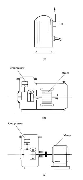
FIGURE 9.14 Hermetic and open-type compressors:
- (a) hermetic; (b) semihermetic; and (c) open.
compressors. A positive displacement compressor increases the pressure of the vapour refrigerant by
reducing the internal volume of the compression chamber through mechanical force applied to the
compressor. This type of refrigeration compressor mainly includes reciprocating, scroll, screw, and
rotary compressors.
The only type of non–positive displacement refrigeration compressor widely used in refrigeration
systems is the centrifugal compressor. In a centrifugal compressor, the increase of the pressure
of the vapour refrigerant depends mainly on the conversion of dynamic pressure to static pressure.
Hermetic, Semihermetic, and Open Compressors
In a hermetic compressor, the motor and the compressor are “sealed” or “welded” in the same housing,
as shown in Fig. 9.14a. Hermetic compressors have two advantages: They minimize leakage of
refrigerant, and the motor can be cooled by the suction vapour flowing through the motor windings,
which results in a small and cheaper compressor-motor assembly.
Motor windings in hermetic compressors must be compatible with the refrigerant and lubrication
oil, resist the abrasive effect of the suction vapour, and have high dielectric strength. Welded
compressors are usually used for small installations from < 1 hp to 24 hp (< 0.7 kW to 18 kW).
Semihermetic compressors are also known as accessible hermetic compressors (see Fig. 9.14b).
The main advantage that semihermetic compressors have over hermetic compressors is accessibility
for repair during a compressor failure or for regular maintenance. Other features are similar to those
of the hermetic compressor. Most of the medium compressors are semihermetic.
In an open compressor, the compressor and the motor are enclosed in two separate housings, as
shown in Fig. 9.14c. An open compressor needs shaft seals to minimize refrigerant leakage. In most
cases, an enclosed fan is used to cool the motor windings by using ambient air. An open compressor
does not need to evaporate the liquid refrigerant to cool the hermetic motor windings. Compared
with hermetic compressors, open compressors may save 2 to 4 percent of the total power input.
Many very large refrigeration compressors are open compressors.
Direct Drive, Belt Drive, and Gear Drive
Hermetic compressors are driven by motor directly or driven by gear trains. Both semihermetic and
open compressors can be driven directly, driven by gear trains, or driven by motor through V belts.
The purpose of a gear train is to increase the speed of the compressor. Gear drive is compact in size
and rotates without slippage. Like belt drive, gear drive needs about 3 percent more power input
than direct-drive compressors. Some large open compressors may be driven by steam turbine, gas
turbine, or diesel engine instead of electric motor.
9.20 PERFORMANCE OF COMPRESSORS
Volumetric Efficiency
The volumetric efficiency ɳvof a refrigeration compressor is defined as
ɳv= Va,v/ Vdis (9.65)
where Va,v = actual induced volume of suction vapor at suction pressure, ft3 (m3)
Vdis= theoretical displacement of compressor, ft3 (m3)
Factors that influence the ɳvof the compressor include:
- Clearance volume and compression ratio Rcom. Both factors affect the volume of reexpansion gas
trapped in the clearance volume.
- Heating effect. When vapour refrigerant enters the compressor, heat absorbed by the vapour results
in a heating effect that increases the specific volume of the refrigerant and, therefore, the Va,v
value.
- Leakage. Refrigerant leaks through the gap and the clearance across the high- and low-pressure
sides of the compressor, such as the clearance between the piston ring and the cylinder in a reciprocating
compressor.
Motor, Mechanical, and Compression Efficiency
Motor efficiency ɳmo is defined as
ɳmo= Pcom / Pmo (9.66)
where Pcom, Pmo _ power input to shaft of compressor and to motor, respectively, hp (kW). Mechanical
efficiency ɳmec is defined as
ɳmec= Wv/ Wcom (9.67)
where Wv, Wcom= work delivered to vapour refrigerant and to compressor shaft, Btu/lb (kJ/ kg).
Compression efficiency ɳcpis defined as
ɳcp= Wisen / Wv (9.68)
where Wisen= work required for isentropic compression, Btu/lb (kJ/kg). Here, Wisen=h2–h1,
where h1 and h2 represent the enthalpy of intake vapour refrigerant and of discharged hot gas, respectively,
in an isentropic compression process, in Btu/ lb (kJ / kg). The difference between work input
on the compressor shaft and work delivered to the vapour refrigerant Wcom–Wvis mainly caused by
the friction loss and turbulent loss of refrigerant flow.
Compressor efficiency ɳcom is the product of ɳcpand ɳmec, that is,
ɳcom= ɳcpɳmec (9.69)
Isentropic and Polytropic Analysis
The isentropic efficiency _isen of a compressor is defined as
ɳisen= h2–h1/ h2’–h1 (9.70)
where h2’= enthalpy of discharged hot gas if compression process is not isentropic, Btu / lb
(kJ/ kg). The difference between h2’ and h2 implies, first, the deviation of a reversible polytropic
process from an isentropic process and, second, the deviation of an irreversible polytropic process
from a reversible process. Isentropic efficiency is equal to compressor efficiency, or ɳisen=ɳcom.
The actual power input to the compressor Pcom, hp, can be calculated as
Pcom= ṁr(h2’–h1’) / 42.41 = ṁr (h2–h1) / 42.41 ɳisen= ṁr (h2 – h1) /42.41ɳcom (9.71)
In Eq. (9.71), ṁr represents the mass flow rate of refrigerant, lb /min (kg/min). For reciprocating
compressors, ṁr can be calculated as
ṁr= pɳvpsuc (9.72)
where p= piston displacement, cfm (or m3/min, p to be covered in Chap. 11)
Psuc= density of suction vapour, lb/ ft3 (kg/m3)
Although the actual compression processes for most compressors are irreversible polytropic
processes, for simplicity, an isentropic analysis is often used. In other words, ɳisen is a widely used
efficiency index for refrigeration compressors, and actual power input to the compressor Pcom is
usually calculated by Eq. (9.71).
Energy Use Index
According to ASHRAE/IESNA Standard 90.1-1999, the following are the current energy use indices
for refrigeration compressors, packaged units, heat pumps, and chillers:
- Energy efficiency ratio (EER) is defined as the ratio of the net cooling capacity of a refrigeration
compressor, a packaged unit, or other device, in Btu/ h, to the electric power input to that device,
in W, under designated operating conditions.
- SEER indicates the seasonal energy efficiency ratio. This is the total cooling capacity of a device
during its normal annual usage period, in Btu, divided by the total electric energy input during the
same period, in watt-hours.
- IPLV indicates the integrated part-load value. This is a single index of merit that is based on partload
EER or COP. It expresses part-load efficiency for refrigeration compressors, packaged units,
and heat pumps based on the weighted operation at various load capacities.
- HSPF indicates the heating season performance factor. This is the total heating output of a heat
pump during its normal annual usage period for heating, in Btu, divided by the total electric energy
input to the equipment during the same period, in watt-hours.
- kW/ ton indicates the electric power consumption of a refrigerating compressor per ton of refrigeration
output. It is a clear and widely used energy index.
From Eq. (9.71) and because ṁr=Qrc/qrf, the kW/ton for a hermetic refrigeration compressor
can be calculated as
kW / ton = 3.516 Win/ qrfɳisenɳmo = 3.516/COPREF (9.73)
where:
Win= work input to compressor (including single-, two-, or three-stage) per lb of refrigerant
flowing through condenser, Btu / lb (kJ /kg)
qrf= refrigeration effect per lb of refrigerant flowing through condenser, Btu / lb (kJ /kg)
ɳisen= isentropic efficiency of compressor
ɳmo= motor efficiency
From Eq. (9.73), primary factors that affect the energy use of the kW/ton index for a refrigeration
compressor are as follows:
- Difference between the condensing and evaporating temperature Tcon _ Tev
- Isentropic efficiency ɳisen or compressor efficiency ɳcom
- Refrigeration effect of the specific refrigerant
The following are the EERs indicating the energy use of a hermetic refrigeration compressor
and motor, and the equivalent COP and kW/ton values:
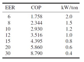
EER is widely used for reciprocating and scroll compressors in air-cooled, direct-expansion refrigeration
systems. The coefficient of performance and kW/ton are usually used for water-cooled
centrifugal chillers. They are often rated at different operating conditions. Water-cooled chillers
always show a more energy-efficient index than air-cooled DX systems.
9.21 SAFETY REQUIREMENTS AND MACHINERY ROOM
Refrigerant Safety
Refrigerant hazards stemming from leaks in the pipe joints, the rupture of system components, and the
burning of escaping refrigerant depend on the type of refrigerant, the occupancy classification, and the
refrigeration system. As discussed in Sec. 9.3, refrigerants can be classified into six safety groups that
range from lower toxicity and no flame propagation (safety group A1) to higher toxicity and higher
flammability (safety group B3). The type of occupancy may be one of the following five categories:
Institutional or health care, such as hospitals and nursing homes
- Public assembly, such as auditoriums and department stores
- Residential, including hotels and apartments
- Commercial, such as offices, restaurants, and markets
- Industrial, such as factories and warehouses
Application Rules for High-Probability Systems
A tightly sealed refrigerant system is always necessary to reduce refrigerant leaks that may produce
refrigerant hazards. In addition, limiting the quantity of refrigerant in a refrigeration system per occupied
space, thereby reducing the possible leaks from joints and seals in a high-probability system,
is an effective means of reducing the hazards of refrigerants for the safety of people and property.
ASHRAE Standard 15-1994 specifies a number of rules and requirements for various refrigerants
in high-probability refrigeration systems. These rules are described in the following paragraphs.
- Any refrigeration system in a room air conditioner or packaged terminal air conditioner
(PTAC), or any small packaged unit for which the refrigerant charge does not exceed 6.6 lb (3 kg),
is considered to meet the system refrigerant safety application requirements.
- Refrigerants that belong to the A1 safety group (HCFC-22, HFC-134a, etc.) and are used in
high-probability refrigeration systems have the following restrictions:
For institutional or health care occupancies (except in kitchens, laboratories, or mortuaries), the
following conditions apply:
- The quantity of refrigerant HCFC-22 in the largest refrigeration system mHCFC-22 is limited to
4.7 lb /1000 ft3 (2.13 kg/28.3 m3) of occupied space.
- The quantity of refrigerant HFC-134a, or mHFC-134a, is limited to 8 lb /1000 ft3 (3.6 kg/28.3 m3)
of occupied space. A flame-sustaining device in an occupied space must be provided with a
hood to exhaust combustion products to open air if the refrigeration system contains more than
1 lb (0.45 kg) of A1 refrigerant (except R-744 carbon dioxide).
For public assembly, residential, and commercial occupancies, the following apply:
- The value of mHCFH-22 in a refrigeration system is limited to 9.4 lb /1000 ft3 (4.3 kg /28.3 m3)
of occupied space.
- The value of mHFC-134a in a refrigeration system is limited to 16 lb /1000 ft3 ( 7.3 kg /28.3 m3)
of occupied space.
In industrial applications, refer to ANSI/ASHRAE Standard 15-1994 for details.
- Refrigerants in the B1 safety group, such as HCFC-123, that are used in high-probability refrigeration
systems should not be allowed for applications involving air conditioning for human
comfort. The quantity of refrigerants in a refrigeration system is limited to under 0.4 lb /1000 ft3
(0.18 kg/28.3 m3) occupied space for commercial occupancy and 0.2 lb /1000 ft3 (0.09 kg/28.3 m3)
occupied space for institutional occupancy.
- Refrigerants in the B2 safety group, such as R-717 ammonia, that are used in high-probability
refrigeration systems are not allowed to be used for institutional occupancy as well as comfort air
conditioning in other occupancies. The following rules apply: When R-717 is used in high-probability
refrigeration systems in process air conditioning (including food storage), mR-717, lb (kg), the
maximum permissible quantity, is limited to the following values:
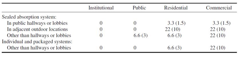
Application Rules for Low-Probability Systems
ASHRAE Standard 15-1994 states the requirements for low-probability refrigeration systems that
have complete, factory-assembled chillers tested by an approved and nationally recognized laboratory
and that are used in health care, public assembly, residential, commercial, and industrial buildings.
The following paragraphs describe these requirements.
- For A1 safety group refrigerants, if mHCFC-22 in the largest refrigeration system exceeds 9.4
lb /1000 ft3 (4.3 kg/28.3 m3) of occupied space or mHFC-134a exceeds 16 lb/1000 ft3 (7.3 kg/28.3 m3)
of occupied space, all refrigerant-containing parts, except pipes and parts located outdoors, must be
installed in a machinery room that meets general safety requirements.
- For B1 safety group refrigerants, if mHCFC-123 in the largest refrigeration system exceeds 0.4
lb /1000 ft3 (0.18 kg/28.3 m3) of occupied space, all refrigerant-containing parts, except pipes and
parts located outdoors, must be installed in a machinery room that meets general safety requirements.
- For B2 safety group refrigerants such as R-717 ammonia, the requirements are as follows:
When mR-717 in the largest refrigeration system exceeds 0.022 lb/1000 ft3 (0.01 kg/28.3 m3) of
occupied space, all refrigerant-containing parts, except pipes and those parts outdoors, must be
installed in a machinery room that meets special requirements; and mR-717 in the refrigeration
system must not exceed 550 lb (250 kg) for institutional occupancy. For details, refer to ASHRAE
Standard 15-1994 and local codes.
Refrigerating Systems of 100 hp (74.6 kW) or Less
Separated fan rooms with light construction and with controlled access by authorized personnel
may contain refrigeration machinery. Refer to ASHRAE Standard 15-1994 and Section 16.6.
Refrigerating Machinery Room
A refrigerating machinery room is an enclosure with tightly fitted doors to safely house compressors,
refrigeration components, and other types of mechanical equipment. A refrigerating machinery
room must be designed so that it is easily accessible, with adequate space for proper servicing,
maintenance, and operation. A refrigerating machinery room must have doors that open outward
and are self-closing if they open into the building; there must be an adequate number of doors to
allow easy escape in case of emergency.
According to ASHRAE Standard 15-1994, a refrigerating machinery room must meet the following
requirements:
- It must be ventilated to the outdoors by means of mechanical ventilation using power-driven fans
or multiple-speed fans. The minimum volume flow rate of mechanical ventilation Vm,v, cfm (L/ s),
required to exhaust the refrigerant from leaks or ruptured component is
Vm,v= 100 mref0.5 (9.74)
where mref is the mass of refrigerant in the largest system, in pounds. When a refrigeration system
is located outdoors, its location is more than 20 ft (6 m) from any building opening, and it is enclosed
by a penthouse or other open structure, then both mechanical and natural ventilation can
be used. The minimum free-aperture section Afa, ft2 (m2), required for natural ventilation of the
machinery room is
Afa= mref 0.5 (9.75)
Provisions for venting catastrophic leaks and component ruptures should be considered.
- For safety group A1 refrigerants such as HCFC-22 and HFC-134a, the machinery room must
include an oxygen sensor to warn the operator when oxygen levels drop below 19.5 percent by
volume. For other refrigerants, a vapour detector should be installed to actuate the alarm and the
mechanical ventilation system.
- There must be no open flames that use combustion air from the machinery room except matches,lighters, leak detectors, and similar devices.A refrigerating machinery room of special requirements must meet the following specificationsin addition to the general requirements:
- Inside the room, there must be no flame-producing device or hot surface continuously operated at
a surface temperature exceeding 800°F (427°C).
- There must be an exit door that opens directly to the outdoors or to a similar facility.
- Mechanical ventilation for ammonia must be either continuously operating or equipped with a vapour
detector that actuates a mechanical ventilation system automatically at a detection level not
exceeding 4 percent by volume.
- It must be provided with remote pilot control panel immediately outside the machinery room to
control and shut down the mechanical equipment in case of emergency.
Because the refrigerating machinery room itself is a fire compartment, the building structure and
its material (including the door, wall, ceiling, and floor) should meet National Fire Protection
Association (NFPA) fire codes. Refrigerating machinery rooms are different from fan rooms where
air-handling units with fans are mounted inside. In a refrigerating machinery room, there are general
and special requirements. The installation of mechanical ventilation and an oxygen or vapour
sensor is mandatory. A central refrigeration plant must be a kind of machinery room.
For more details, refer to ASHRAE Standard 15-1994.
Storage of Refrigerants
Refrigerants are usually stored in cylinders during transport and while on site. During storage, the
pressure of the liquid refrigerant must be periodically checked and adjusted. Excessive pressure
may cause an explosion. According to Interstate Commerce Commission (ICC) regulations, liquid
refrigerants must not be stored above 130°F (54.4°C), although the containers are designed to withstand
up to 3 times the saturated pressure at 130°F (54.4 °C). If a container bursts, liquid refrigerant
flashes into vapor. Such a sudden expansion in volume could cause a violent explosion inside a
building, blasting out windows, walls, and roofs.
Containers should never be located near heat sources without sufficient ventilation. They must
also not be put in a car or truck in direct sunlight. The valve of the container is attached by thread
only. If the threads are damaged, the force of escaping vapour could propel the container like a
rocket.
According to ASHRAE Standard 15-1994, in addition to the refrigerant charge in the system
and receiver, refrigerant stored in a machinery room shall not exceed 330 lb (150 kg). The receiver
is a vessel used to store refrigerant after the condenser when necessary.
REFERENCES
ARI, Switch from CFC Chillers Is Slower Than Projected, ASHRAE Journal, no.6, 1997, pp. 11–12.
ASHRAE, ASHRAE Handbook 1998, Refrigeration, ASHRAE Inc., Atlanta, GA, 1994.
ASHRAE, ASHRAE Standard 15-1994, Safety Code for Mechanical Refrigeration, Atlanta, GA, 1998.
ASHRAE, ASHRAE Handbook 1997, Fundamentals, Atlanta, GA, 1997.
ASHRAE, ANSI/ASHRAE Standard 34-1997, Number Designation and Safety Classification of Refrigerants,
Atlanta, GA, 1997.
Bivens, D. B, Allgood, C. C., Rizzo, J. J., Shiflett, M. B., Patron, D. M., Shealy, G. S.,Yokozeki, A.,Wells,W.
D., and Geiger, K. A., HCFC-22 Alternative for Air Conditioners and Heat Pumps, ASHRAE Transactions,
1994, Part II, pp. 566–572.
Corr, S., Dekleva, T. W., and Savage, A. L., Retrofitting Large Refrigeration Systems with R-134a, ASHRAE
Journal, no. 2, 1993, pp. 29–33.
Cox, J. E., and Miro, C. R., Industry Helping U.S. Comply with Laws Governing CFCs, ASHRAE Journal,
- 12, 1996, pp. 26–27.
Denny, R. J., The CFC Foot Print, ASHRAE Journal, November 1987, pp. 24–28.
Dooley, E. W., Industry Status of CFC Chiller Retrofits and Replacements, HPAC, no. 1, 1997, pp. 131–135.
Dossat, R. J., Principles of Refrigeration,Wiley, 2d ed., New York, 1978.
Gilkey, H. T., The Coming Refrigerant Shortage, Heating/Piping/Air Conditioning, April 1991, pp. 41–46.
Hickman, K. E., Redesigning Equipment for R-22 and R-502 Alternatives, ASHRAE Journal, no. 1, 1994,
- 43–47.
Hwang,Y., Judge, J., and Radermacher, R., Experience with Refrigerant Mixtures, ASHRAE Transactions, 1997,
Part I, pp. 765–776.
King, G. R., Modern Refrigeration Practice, 1st ed., McGraw-Hill, New York, 1971.
Lavelle, J., HFCs Will Find Greater Use as CFCs Diminish, Air Conditioning, Heating & Refrigeration News,
Feb. 17, 1997, p. 25.
Linton, J. W., Snelson,W. K., Triebe, A. R., and Hearty, P. F., System Performance Comparison of R-507 with
R-502, ASHRAE Transactions, 1995, Part II, pp. 502–510.
Lowe, R., and Ares, R., From CFC-12 to HFC-134a: An Analysis of a Refrigerant Retrofit Project,
Heating/Piping/Air Conditioning, no. 1, 1995, pp. 81–90.
McGuire, J., An Industry at Risk, User Concerns, ASHRAE Journal, August. 1988, pp. 48–49.
Parker, R.W., Reclaiming Refrigerant in OEM Plants, ASHRAE Transactions, 1988, Part II, pp. 2139–2144.
Parsnow, J. R., The Long Term Alternative: R-134a in Positive Pressure Chillers, ASHRAE Journal, no. 5, 1993,
- 54–56.
Powell, P., Recips on Decline, Gas-Electric Power Ploys, Secondary-Loop Hoopla: Top Mechanical Focus, Air
Conditioning, Heating & Refrigeration News, June 16, 1997, pp. 22–26.
Rowland, S., The CFC Controversy: Issues and Answers, ASHRAE Journal, December 1992, pp. 20–27.
Smith, N. D., Ratanaphruks, K., Tufts, M. W., and Ng, A. S., R-245ca: A Potential Far-Term Alternative for
R-11, ASHRAE Journal, no. 2, 1993, pp. 19–23.
Smithart, E. L., and Crawford, J. G., R-123: A Balanced Selection for Low Pressure Systems, ASHRAE Journal,
- 5, 1993, pp. 66–69.
Snelson,W. K., Linton, J. W., Triebe, A. R., and Hearty, P. F., System Drop-In Tests of Refrigerant Blend
R-125/R-143a/R-134a (44%/52%/4%) Compared to R-502, ASHRAE Transactions, 1995, Part I, pp. 17–24.
Stamm, R.H., The CFC Problem: Bigger Than You Think, Heating, Piping and Air Conditioning, April 1989,
- 51–54.
Swers, R., Patel,Y. P., and Stewart, R. B., Thermodynamics Analysis of Compression Refrigeration Systems,
ASHRAE, New Orleans, LA, January 1972.
Tan, L. C., and Yin, J. M., The Exergy-Enthalpy Diagram and Table of R-22 and Their Application, ASHRAE
Transactions, 1986, Part I A, pp. 220–230.
Tuck, A., The Chemistry of Stratospheric Ozone Depletion, HPAC, no. 1, 1997, pp. 111–116.
Wang, S. K., Principles of Refrigeration, vol. 1, 1st ed., Hong Kong Polytechnic, 1984.
Wilson, D. P., and Basu, R. S., Thermodynamics Properties of a New Stratospherically Safe Working Fluid—
Refrigerant 134A, ASHRAE Transactions, 1988, Part II, pp. 2095–2118.
This information is for reference only. Please be aware that some of the details it con may now be obsolete, have been superseded or updated.
At Broughton EAP we have four decades worth of experience in the design, manufacture and supply of portable air conditioning units, industrial electric fan heaters, refrigerant dehumidifiers and cooling and ventilation fans. Over the years we’ve worked with the countries leading climate control hire specialists, famous drinks manufacturers, large data centres and even local village halls, and we like to think everything we’ve learnt working with that diverse group is what gives us an edge. Not only can we deal with the specialists but we’re also happy looking after the smaller client whose application might not be huge but is still just as important.
For full details on our range of portable air conditioning units, industrial electric fan heaters, dehumidifiers and ventilation fans please check out our site, call +44 (0)1527 830610 or email sales@broughtoneap.co.uk.