Electric motors are used to drive the fans in our industrial electric fan heaters, ventilation fans, cooling fans and even our large portable air con units and fan coil units. An essential component in almost all industries, motors are particularly relevant to HVAC manufactures as it’s an industry reliant on air movement via fans and even the compressors in portable air conditioners use motors, as do the circulation pumps in our packaged portable electric boilers.
Electric motors:
Different kinds of motors:
There are many kinds of electrical motors which can be divided into two main categories: DC motors, where DC stands for direct current and AC motors where AC stands for alternating current. The AC motors can be divided in two sub categories, synchronous motors and asynchronous motors. A synchronousmotor shaft is rotating at the same speed as the rotating magnetic field inside the motor whereas an asynchronous motor rotates at a slower rate compared to the rotating magnetic field.
Small DC motors are used in cordless tools, small toys and disk computer drives, however, bigger DC motors are still used in some industrial applications.
AC motors are mainly used for industrial applications such as centrifugal pumps, fans, compressors etc. but can also be found in some household appliances such as washing machines.
By far the most commonly used AC motor is the induction motor. There are two types of induction motors, one with wound type rotor, also called slip-ring motor and another one with squirrel-cage rotor.
Components of an induction Motor:
As the Motor is made up of several parts, this chapter will serve the purpose to show what the parts look like and what they are called. There will also be a brief explanation to what is the purpose of the part that is described.
Outer parts:
The stator house holds the stator package and protects the active inner parts from the environment. Another task of the stator house is to help with the heat transfer from inside the motor to the outside, this is the reason why motors often have cooling ribs to increase the surface area for better heat dissipation.
The mounting feet and lifting lugs can be found on the stator house. In both ends of the stator house there is the end shields that secure the bearings holding the shaft and protecting the inside of the motor from the environment.
On top of the motor lies the terminal box that houses the connectors which is used for connecting the motor to the electrical supply. It also serves to protect the connectors from water and dust and to protect against live electrical parts.
Coming out of the end shield on one side is the shaft end that transmit torque from the motor to the driven application. The opposite side is referred to as non-drive end or ND end. In the non-drive end we have the fan cover to protect the fan that is mounted on the shaft and also direct the air flow created by the fan over the motor house. At the same time it protects humans, animals and objects from getting in contact with the rotating fan.
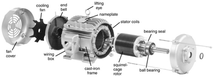
Figure 1. Outer Parts of a motor
Inner parts:
The stator core is fixed inside the motor frame and is made of laminated electrical steel sheets. The stator core has slots that are filled with copper windings. Its purpose is to create a rotating magnetic field.
The rotor is the rotating part of the motor and is made of a steel core with aluminium windings. With the use of the rotating magnetic field from the stator, the rotor is able to produce torque.
The rotor body is attached to the shaft in order to transmit the created torque from inside the motor to the driven application.
The rotor and stator together form the active parts of the motor.
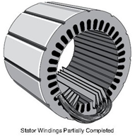
Stator:
The stator core consists of several electrically laminated steel sheets which are fixed together to form the stator core. These laminated steel sheets are designed so that when fixed they create slots inside the stator core.
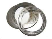
Figure 3. Stator steel sheets
The winding coil is then inserted into the slots of the stator core. Laminated sheets are used to reduce the induced current in the stator which leads to overheating of the motor and energy losses that could be used for creating the magnetic field instead. This unwanted induced current is also called eddy current.
Rotor:
The rotor is the rotating part of the motor and can be found inside the stator. As with the stator, also the rotor core consists of electrically laminated steel sheets. Inside the rotor slots there are aluminium windings that are casted together with short-circuit rings.
This is done by making holes in the lamination so that when they are stacked, channels will be formed through the rotor core. During the casting these channels will fill up with aluminium and form the windings that together with the short-circuit rings are shaped like a squirrel cage. Hence the name squirrel cage induction motor.
The windings inside the rotor do not go straight but are skewered for the purpose of reducing electrical noise and vibration. The rotor core helps conducting the magnetic field from the stator to the rotor windings.
There is an air gap between the stator and the rotor and since it is known that air conducts magnetic fields poorly the gap can’t to be too big. The airgap cannot either be too small since metallic objects expand when heated and as the rotor gets warm there will not be enough space for it to rotate inside the stator. The rotor windings can also be called for rotor bars.
Next up is explaining how the rotor is able to spin inside the stator but first electromagnetic induction has to be explained.
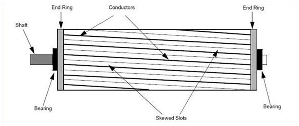
Figure 5. Squirrel cage rotor
Theory about electromagnetism:
This chapter will explain how electromagnetism works and how it is used to make an electrical motor to rotate.
Magnets and magnetic fields:
A magnet is an object or material that creates a magnetic field. Magnetic fields are an invisible force that attracts ferromagnetic metals such as iron, steel, nickel and cobalt. Magnets have two poles, a north pole and a south pole. The magnetic field travels from the North Pole to the South Pole.
The magnet also attracts or repels other magnets depending on which way the poles are facing. If the poles are of the opposite polarity, they will attract each other. If the poles are of the same polarity, they will repel each other.
This information is relevant for understanding the induction motor.
There are two kinds of magnets, permanent magnets and electromagnets. Permanent magnets can be of two types.
They can be made from rare-earth magnet materials like neodymium-iron-boron or be of ferromagnetic type where a ferromagnetic object like iron have been magnetized to have a persisting magnetic field.
Electromagnets are temporary magnets created with the use of a current and a ferromagnetic core such as iron.
The biggest advantage of these electromagnet is that they can be controlled by a current.
Electromagnets:
A wire that conducts a current creates a magnetic field that will wrap itself around the wire, this idea is used in creating electromagnets.
Use your right hand fingers to determine which way the magnetic field will rotate if you place your thumb in same direction as the current in the wire.
This rule can also be used to determine which is the South and North Pole in an electromagnet. This rule is called the right-hand rule. If the current switches direction in the wire, the magnetic field will also switch direction.
Electromagnets are created by wrapping a conducting wire around an iron core and send a current trough the wire. Now the iron core will act as a magnet.
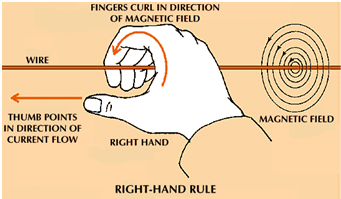
Figure 6. Right-Hand rule
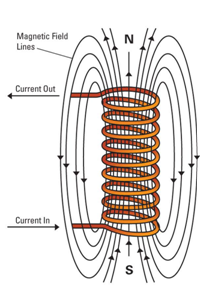
Figure 7. Electromagnet
If we use DC in the wire, the magnet has a stationary north and South Pole. If we use AC, the direction of the current will change with the sinusoidal wave so 50 times a second if connected to a 50Hz supply. This means that the direction of the magnetic field created also will change as often, and the pole polarity will shift 50 times a second as well. Electromagnets can be turned on and off by controlling the current.
An electromagnet does not need an iron core but it helps conducting the magnetic field and “boosts” the power of the electromagnet as a magnetic field flows very poorly in air.
The windings and the core in the stator acts as electromagnets which in turn creates magnetic fields.
Electromagnetic induction and Lorentz force:
The principal of electromagnetic induction is that a current will be induced in a closed electrical circuit when exposed to a changing external magnetic field.
It also holds true that a closed electrical circuit that is conducting a current and is exposed to an external magnetic field will be affected by a force and start to move in the direction the fingers point in Figure 8. That force is called the Lorentz force and is a base principle on how an electrical motor works.
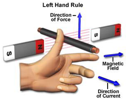
Figure 8. Left Hand Rule
How the motor spins:
The following section will explain what makes the motor rotate for a three phase AC induction motor. In Figure 9 the stator slots are illustrated by the small circles and the black lines illustrates the coils in one phase of the stator winding.
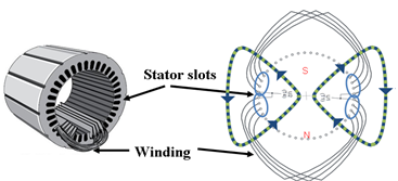
Figure 9. Stator windings and magnetic fields
The first phase winding is divided into two coils using eight slots each so a total of sixteen. For each coil four are used for going in, marked U1 and four for coming out marked U2. Notice that the number of slots in the stator will always be a multiple of 6 because the 3-phase coils will always use one slot going in and one coming out.
Now when voltage is connected a current starts running through the coils and this will create a magnetic field around the coil in the slot. The magnetic field is shown as green and blue striped lines in the picture above.
Applying the right hand rule will show that the direction of the magnetic field around the slots where the phase goes in will be clockwise and around the slots where it comes out it will be counter clockwise. This is how an electromagnet with a north and South Pole in the induction motor is created. As this motor only creates one north and one South Pole it’s concluded that this is a two pole motor.
The stator core and especially the part between the slots usually referred to as the stator teeth will act as the core of the electromagnet and help transfer the magnetic field onto the rotor. The stator core is used for two reasons. The first reason is to keep the winding coils in place. The second reason is to help conduct the magnetic field. Now, one phase only is not going to make a motor so the other two phases have to be added. Add the same amount of coils for phase 2 and phase 3 which are indicated with the colours green and red.
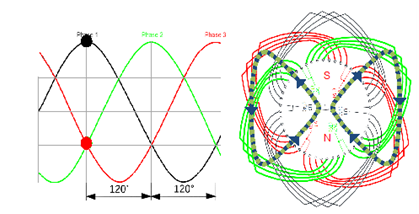
These two phase coils have their coil ends marked V1-V2 and W1-W2. The coloured dots indicates the current in each phase. As the phases are fed with AC the currents direction varies all the time in a sinusoidal curve pattern.
Now as the current changes direction all the time its power to create the magnetic field will vary according to the sinusoidal curve pattern.
That means if phase 1 had the highest current value it will soon change direction and drop. Next in line will be phase 3 that reaches its peak current and the magnetic field will move onto phase 3 coils and then later to the phase 2 coils. This means that the magnetic field will start to rotate counter clock-vice in the stator.
Switching the phases that are coming from the electrical network so that phase 2 becomes high after phase 1, the magnetic field will rotate the other way. Each phase will have its own coils and depending on the size of the motor the amount of slots used for one phase will vary. As the diameter of the stator core increases the number of stator slots also increases. The phase coils will then be repeated to fill all slots to meet the desired pole number.
So with the use of AC we can get a rotating magnetic field in the stator. As we now have a rotating magnetic field projected onto the rotor from the stator. The rotor bars are currently standing still but because of the moving magnetic field, a current will be induced in the rotor bars. Now that we have a current in the rotor bars and the magnetic field from the stator, the rotor bars will be affected by Lorentz force and start to spin in the same direction as the rotating magnetic field.
The motor is called an asynchronous motor because the rotor doesn’t spin with the same speed as the rotating magnetic field. How much slower the rotor rotates compared to the rotating field is called the slip. With no load on the motor the slip is close to zero. However as we increase the load on the motor, the slip also increases and If the slip gets too big the motor stalls.
Magnetic poles and rotating speed of the motor:
This chapter will explain how the number of magnetic poles in the motor and the frequency of the current will affect the rotating speed of the motor.
Magnetic poles:
To the left is the picture of the two pole motor that we have been using so far.
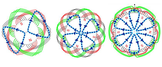
Figure 11. Motors with different amount of poles
In this motor each phase has two coils, and this resulted in one North Pole and one South Pole. So one pole pair or two poles
In the picture in the middle each phase has four coils. Double the amount of coils compared to the two pole motor. That means it has two north poles and two south poles which results in two pole pairs or four poles.
Now continue to increase the amount of poles by adding more and more coils for each phase like in the right picture. To create a six pole motor use six coils per phase that creates three north poles and three south poles and so on.
The number of stator slots is always a multiple of six. When it comes to the pole number it’s always a multiple of two because the north and the South Pole always come in pairs. It’s not possible to create a north pole without creating a south pole and vice versa. When talking about motors remember not to mix up the number of poles with the number of pole pairs. A combination of the frequency of the current and number of poles in the motor is what decides the rotating speed of the motor.
Rotating speed of the motor:
As was said earlier the AC shift direction 50 times per second if it is a 50Hz power supply. Looking at the diagram, all the three phases will reach their peak on both the positive and negative side fifty times per second. This means that the magnetic field will rotate fifty times per second in a two pole motor as it has only one pole pair.
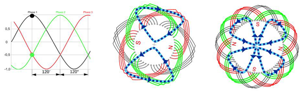
Figure 12. Rotating magnetic field in a stator
As the rotating speed of a motor is given in revolutions per minute. This means that if the magnetic field rotates 50 times in one second it will rotate 3000 times in one minute. The real rotation speed of the asynchronous motor will always be a bit slower because of the slip.
Now with a four pole motor which means two pole pairs. It will take double the time for the magnetic field to travel around the stator as it has double the amount of winding coils for each phase. So with a frequency of 50Hz the magnetic field rotates with a speed of 25 revolutions per second which means it will rotate 1500 times in one minute.
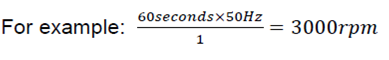
It’s possible to calculate the speed of a motor with any given amount of pole pair number with the following formula.
![]()
Take 60 seconds times the frequency of the AC power supply used divided by the number of pole pairs in the motor equals to the rotation speed of the motor given as revolutions per minute.
AC with a frequency of 50Hz gives these magnetic field rotation speeds depending on the amount of pole pairs in the motor.
| Approximate Electrical Motor Speed (rpm) | ||||
| No. Poles | Speed with Rated Load | Synchronous Speed (no Load) | ||
| 60 Hz | 50 Hz | 60 Hz | 50 Hz | |
| 2 | 3450 | 2850 | 3600 | 3000 |
| 4 | 1725 | 1425 | 1800 | 1500 |
| 6 | 1140 | 950 | 1200 | 1000 |
| 8 | 850 | 700 | 900 | 750 |
50Hz and 60Hz are the standards used by various countries. The reason why there are different amount of poles is that the poles determine the rotation speed of the magnetic field which in turn decides the rotation speed of the motor.
The more poles, the slower the motor will spin. So now it is possible to choose between a higher rotating speed anda greater torque production based on what applications the motor will be used for.
The fewer the pole pairs the faster the rotation. The more the pole pairs the higher the torque. The more the pole pairs the quieter the motor. 2 pole motors tend to be quite noisy.
An 8 pole motor will deliver 4 X the torque of a 2 pole motor.
Star and Delta connection:
Connecting a motor to the power supply can be done in two ways. Either use star connection or Delta connection. The U1-U2, V1-V2 and W1-W2 that marks the coil ends of the three different phases that is present on the terminal block of the motor. The L1, L2 and L3 represent the three phases coming from the electrical network.
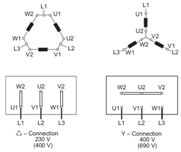
Figure 13. Delta and Star Connection
A Delta connection is when the phase coils are connected across with connection bars and then later connected to L1, L2 and L3 according to Figure 13.
A Wye connection is when one side of all three phase coils are connected together with connection bars and the other side is connected to L1, L2 and L3 according to the picture above.
The difference between star and delta connection is the difference in voltage over the phase windings. For example when a 400V supply is connected to L1, L2 and L3 on the delta connected motor there is 400V over the different phases, meaning 400V between U1 and U2, 400V between V1 and V2 and also W1 and W2. But when the motor connected in star, it will still have 400V between L1 and L2 but only have 230V volts over each phase winding U1 to U2 and so on.
So in the star connected motor the network voltage divided by the square root of 3 (1.73) over each phase winding while the delta connection have the same voltage as the network over the phase windings.
A lower voltage over the phase windings will also give a lower current in the windings.
As the ratio between star and delta connection is always the square root of 3, this means that a motor with a winding optimised for 400V delta could be connected in star to a 690 volt network and give the same performance, or a motor made for 400 volt star could also be used for 230 volt delta.
This is many times used in the industry where part of the factory might be running on 690 volt and other parts on 400 volt.
If we were to supply the motor insufficient voltage, it will simply not start or it will not be able to handle the load. If we supply the motor with a higher voltage than it can handle, the circuit breakers will trip.
Starting methods:
When starting a motor it’s possible to do in several ways
1. Direct on line start
2. Star delta connection start
3. Transformer start (not used at Broughton)
4. Soft starter (not used at Broughton)
5. Variable speed drive start (not used at Broughton)
Direct on line start
When starting a motor direct on line the electrical supply voltage is directly going to the motor.
It is the simplest starting method, however the starting current can be as high as 8 times the nominal current as the motor requires additional current while the rotor magnetises during start up.
In some scenarios one might want to have a lower starting current and that can be achieved with the use of the other starting methods.
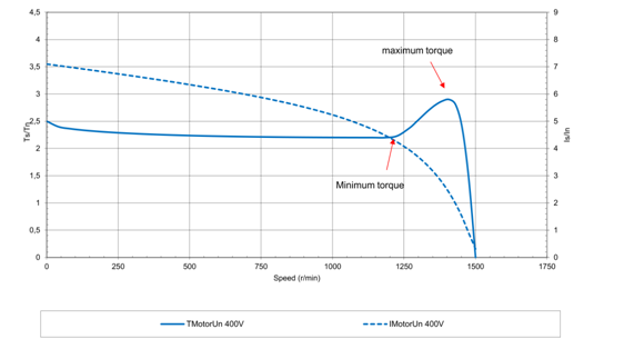
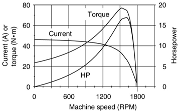
Figure 14. Direct on line start graph
In Figure 14, the dotted line shows the current and the filled line shows the torque. Seeing the starting current is seven times the nominal current for an example motor with direct on line starting method, but as the motor picks up speed the need of magnetizing current decreases down to the nominal current.
During the ramp-up of speed, the value of the torque changes. Depending on the rotor slot design and materials used.The form of this curve can also vary.
𝑇𝑠 or starting torque as explained above. In addition to this, there is also minimum torque or pull up torque, meaning the point on the starting torque curve with the lowest value. This point is usually the factor determining if the motor will be able to start when the load from the application is applied.
Also we have the maximum torque or break down torque. This is the highest point on the starting torque curve. When the motor is in continual running you can overload it to the limit of the maximum torque before it stops. This would only be possible for a short time in practice as it will make the motor heat too much if overloaded for a longer period of time.
𝐼𝑠 stands for starting current and is the number of amperes drawn by the motor from the supply at the time of starting before the shaft has started to turn. 𝐼𝑛is the nominal current drawn from the supply at full speed when loaded at its rated power. The starting current curve falls as the speed of the motor is picking up, this is due to the rotor finding its place in the rotating magnetic field and decreasing its slip. During start up the motor needs a lot of current to magnetize the rotor but as the speed picks up the magnetizing current decreases.
Star delta connection start:
In some scenarios one might want to have a lower starting current. This can be achieved with the use of a star delta start.
The star delta starter uses the star connection of the motor windings when starting and after a while it switches to delta connection, typically when the full speed has been achieved. This can reduce the starting current so it’s only one third compared to the previous starting current.
Since it gives a lower starting current it also means it gives a lower starting torque which can be useful in some applications, but just as well could it make starting impossible in others so this needs to be checked prior to using such arrangements.
Figure 15 is a graph to compare starting current and starting torque for star delta start and Direct on line start.
The blue curves are for the Direct on line start and the red curves are for the start delta start. The dotted lines represent starting current and filled lines represents starting torque. There is a lower starting current and starting torque with star delta start compared to direct on line start.
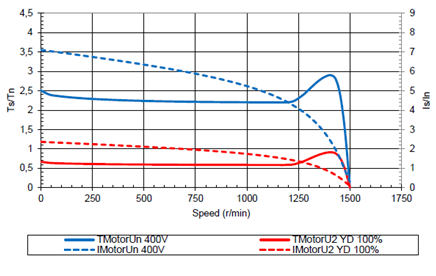
Figure 15. Star delta connection start graph
Transformer start
(Not covered)
Soft start
(Not covered)
Variable speed drive start
(Not covered)
1-phase induction motor:
The 1-phase motor has the same rotor design as the 3-phase motor but the windings in the stator are a bit different. There are a number of different types of 1-phase motors but this chapter will focus on explaining how the permanent split capacitor motor works.
Since the motor is now only fed with 1-phase AC instead of 3-phase AC, the motor can still create a magnetic field that switches direction in the motor windings, but since the motor has no phase shift it can’t create the rotating magnetic field in the stator as it did on the 3-phase motor. This problem is solved by dividing the motor windings into two windings, a primary winding and a secondary (auxiliary) winding.
On the secondary winding a capacitor is connected. By connecting the capacitor on the secondary winding, the current on the primary and secondary winding doesn’t change direction at the same time. In other words it will create a phase shift close to 90 degrees between the two. This will now create a rotating magnetic field just like in the 3-phase motor but with two phases instead of three.
That means if the primary winding had the highest current value it will soon change direction and drop. Next in line will be the secondary winding that reaches its peak current and the magnetic field will move onto the secondary winding coils and then back to the primary winding coils. One can reverse the rotation of the motor by switching the capacitor to the primary windings according to Figure 17. So with only one phase the motor can still get two separate phase windings and a rotating magnetic field.
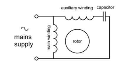
Figure 17. 1-phase induction motor winding schematic
The rotating magnetic field will not be as strong as the one in the 3-phase motor and thus the motor will get a lower break down torque.
Other typical 1-phase motor types are, Capacitor start induction run which means the secondary windings are only used in the start. Capacitor start and run which means it will have an extra capacitor in the start compared to permanent split capacitor in order to further increase the starting torque.
As with a 3-phase motor we can also create a motor with different amount of pole pairs. It’s possible to control the rotation speed of a 1-phase motor.
Shaded Pole Motors:
A Shaded Pole motor is an AC single phase induction motor and can generally be found in our FF3 industrial fan heaters and CR commercial dehumidifiers. The auxiliary winding, which is composed of a copper ring, is called a shading coil. The current in this coil delays the phase of magnetic flux in that part of the pole in order to provide a rotating magnetic field. The direction of rotation is from the unshaded side to the shaded ring.
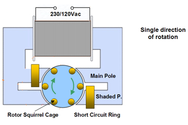
- This shading-coil (ring) arrangement displaces the axis of the shaded poles from the axis of the main poles.
- When power is applied to the stator, the flux in the main part of the pole induces a voltage in the shading coil, which acts as a transformer secondary winding.
- Since the current in the secondary winding of a transformer is out of phase with the current in the primary winding.
- The current in the shading coil is out of phase with the current in the main field winding.
- Thus, the flux of the shading pole is out of phase with the flux of the main pole.
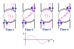
Rotating field of a Shaded Pole Motor
Shaded pole motors have advantages and disadvantages and are only used in low power applications.
- They are relatively simple motos and are cheap to product
- They do not require a capacitor to start
- Shaded pole motors have a low efficiency
- Low starting torque
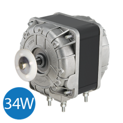
Shaded pole motor. Typically used as a fan motor on low powered heaters and on dehumidifers
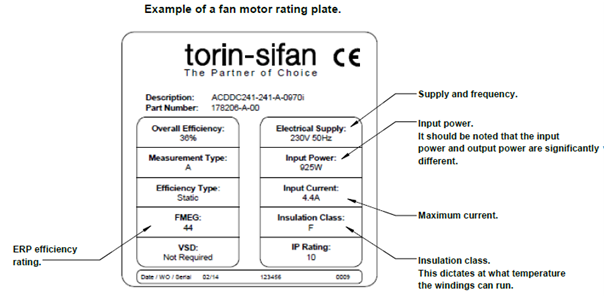
Motor rating plates
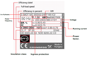
Sample rating plate for a 3 phase motor
Comparisons between a 2 pole fan motor assembly and a 4 pole fan motor:

2 pole 200mm axial fan
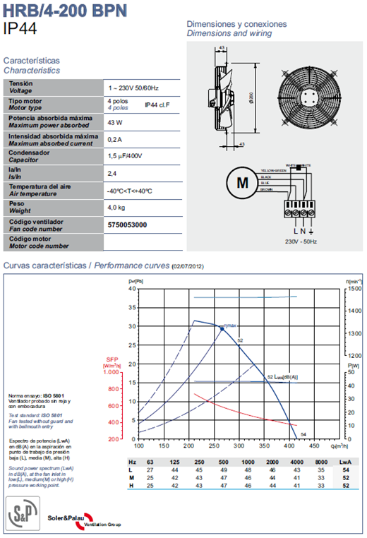
4 pole 200mm axial fan
With over four decades experience in the design, manufacture and supply of large fan heaters, industrial portable air conditioning units, cooling fans, ventilation fans, portable air conditioning units, cooling fans, ventilation fans, portable boiler packages, dehumidifers and associated climate control equipment, Broughton EAP Ltd are able to offer an unrivalled expertise. For full details on the Mighty Cool air conditioners, Mighty Breeze fans, CR dehumidifiers, Fire Flo large fan heaters and our other equipment please visit our site of call 01527 830610.