Here at Broughton extensive range of portable industrial electric heaters are available in a variety of voltages: 110V, 230V and 400V with the options of 1.5kW, 3kW, 9kW, 15kW, 18kW, 22kW and 42kW heat outputs. The range includes infrared and fan heater models so there’s something to suit any application.
The one thing our industrial fan heaters and infrared heaters have is that they’re all electric heaters, which can be plugged into a suitable supply, such as 230V single phase or 400V three phase to produce heat, rather than burn diesel or paraffin. In this section of the site we’ve looked at the basic theory behind power generation and how it relates to industrial fan heaters and infrared heaters.
Introduction
All matter is comprised of molecules. The molecule is the smallest quantity of a substance that can exist and still display all the physical and chemical properties of that substance. Molecules are made up of smaller particles called atoms of which there are over a hundred different types. All molecules consist of various combinations of atoms. For example, two atoms of hydrogen and one of oxygen form one molecule of water, and sulphuric acid is made up of two atoms of hydrogen, one of sulphur and four of oxygen. Atoms consist of a relatively heavy, positively charged core or nucleus, around which a number of much lighter negatively charged electrons move in one or more orbits. One type of atom differs from another in the number of protons (positively charged particles) and neutrons (particles that do not have either a positive or negative charge) which make up the nucleus, and in the number of negatively charged electrons which continually orbit the nucleus. The orbiting electrons are arranged in one or more orbits, depending on how many electrons the atom has. The more electrons there are, the greater the number of orbits. It is sometimes possible for an electron to become detatched from an atom, especially if it is the only electron in the outermost orbit.
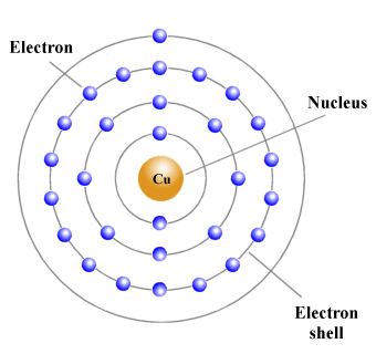
The ease with which electrons can be detached from their parent atoms varies from one substance to another. In some substances there is continual random movement of electrons from one atom to another, and the application of a voltage across a piece of wire made of such a substance (for example from a battery) will cause some of these free electrons to flow along the wire in one direction, producing an electric current. The electrons in the outermost orbit (or shell) of an atom are called valence electrons. If the outer shell has a full complement of electrons, it is very difficult to knock one of these valence electrons out of its orbit, and they are said to be tightly bound to the atom. Materials with such a structure do not conduct electricity easily (i.e. they are insulators). If there are only one or two valence electrons, however, the bond between the electron and the atom is much more easily broken, and there will be far more free electrons moving around within the material, making it a conductor.
In metals such as copper, the valence electrons are held only loosely by their atoms and can move from one atom to another. The motion of these free electrons within the material is usually random, but if a force acts on the free electrons in a metal wire such that they all flow along the wire in the same direction, an electric current is produced. When this happens, the wire may get warm, and the needle of a magnetic compass brought into close proximity to the wire can be deflected because a magnetic field is created in the space surrounding the wire. A constant flow of electrons in one direction is called a direct current (abbreviated to dc).
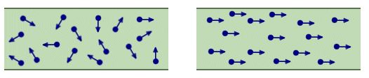
Electrons moving randomly (left) and electrons acted on by a force (right)
Current can be likened to the flow of water through a pipe, and is measured in amperes (A) by connecting an ammeter so that the current flows through it. The current is said to have a value of one ampere (1A) when approximately 6,000,000,000,000,000,000 (6 × 10¹⁸) electrons pass any point in a wire in one second. The currents used in the circuits that are found in most electronic devices tend to be very small. For this reason you will often come across current values expressed in smaller units such as milliamperes and microamperes. One milliampere (1 mA) is one thousandth (1 × 10⁻³) of an ampere. One microampere (1 µA) is one millionth (1 × 10⁻⁶) of an ampere. By convention, the direction of current flow is said to be from positive to negative (hence the term conventional current). Materials that conduct electricity are called conductors, and include all metals. Materials that do not conduct electricity are called insulators.
A battery can provide the force required to cause a current to flow in a wire. The battery produces an electromotive force (EMF) due to the chemical action that occurs inside it. Electromotive force is measured in volts (V) by connecting a voltmeter across the battery. Batteries produce direct current, and the EMF acts along a wire at almost the speed of light (3 × 10⁸ metres per second) and causes the free electrons to drift in one direction around an electrical circuit. The electrons themselves actually drift quite slowly, often travelling at less than one millimetre per second.
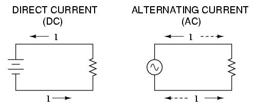
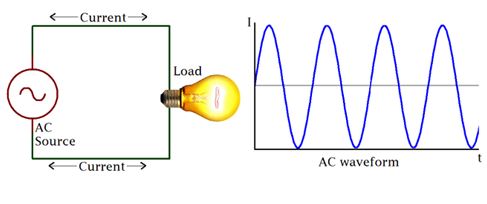
An electrical circuit is a complete conductive path through which electrons flow from the source to the load and back to the source. The direction and magnitude of the electrons flow however depend on the kind of source. In Electrical Engineering, there are basically two types of voltage or current (Electrical Energy) source which defines the kind of circuit and they are; Alternating Current (or voltage) and Direct Current.
AC Circuits
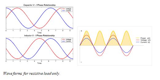
AC circuits as the name (Alternating Current) implies are simply circuits powered by an Alternating Source, either voltage or current. An Alternating Current or Voltage, is one in which the value of either the voltage or the current varies about a particular mean value and reverses direction periodically.
Most present day household and industrial Appliances and systems are powered using alternating current. All DC based plugged in appliances and rechargeable battery based devices technically run on Alternating current as they all use some form of DC power derived from AC for either charging of their batteries or powering of the system. Thus Alternating current is the form via which power is delivered at the mains.
The Alternating circuit came into being in the 1880s when Tesla decided to solve the long range incapability of the Thomas Edison’s DC generators. He sought a way of transferring electricity at a high voltage and then employ the use of transformers to step it either up or down as may be needed for distribution and was thus able to minimize power loss across a great distance which was the main problem of Direct Current at the time.
The major difference between the AC and DC, which is also the cause of their different characteristics, is the direction of flow of electric energy. In DC, Electrons flow steadily in a single direction or forward, while in AC, electrons alternate their direction of flow in periodic intervals. This also leads to alternation in the voltage level as it switches along from positive to negative in line with the current.
Basic AC Source (Single Coil AC Generator)
The principle around AC generation is simple. If a magnetic field or magnet is rotated along a stationary set of coils (wires) or the rotation of a coil around a stationary magnetic field, an Alternating current is generated using an AC generator(Alternator).
The simplest form of AC generator consists of a loop of wire that is mechanically rotated about an axis while positioned between the north and south poles of a magnet.
Consider the Image below.
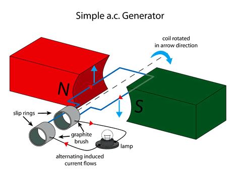
As the armature coil rotates within the magnetic field created by the north and south pole magnets, the magnetic flux through the coil changes, and charges are thus forced through the wire, giving rise to an effective voltage or induced voltage (Induction). The magnetic flux through the loop is as a result of the angle of the loop relative to the direction of the magnetic field. Consider the images below;
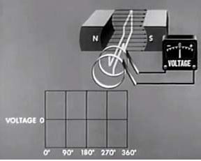 AC generator Armature at 0 degrees
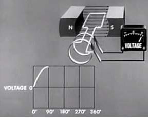 AC generator Armature at 90 degrees
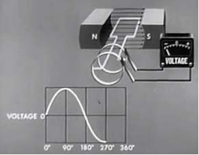
 AC generator Armature at 180 degrees
 AC generator Armature at 270 degrees
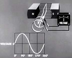 AC generator Armature at 360 degrees
Electromagnetic Induction:
When a DC current passes through a long straight conductor a magnetising force and a static magnetic field is developed around it. If the wire is then wound into a coil, the magnetic field is greatly intensified producing a static magnetic field around itself forming the shape of a bar magnet giving a distinct North and South pole.
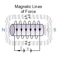
Air-core Hollow Coil
The magnetic flux developed around the coil being proportional to the amount of current flowing in the coils windings as shown. If additional layers of wire are wound upon the same coil with the same current flowing through them, the static magnetic field strength would be increased.
Therefore, the magnetic field strength of a coil is determined by the ampere turns of the coil. With more turns of wire within the coil, the greater the strength of the static magnetic field around it.
But what if we reversed this idea by disconnecting the electrical current from the coil and instead of a hollow core we placed a bar magnet inside the core of the coil of wire. By moving this bar magnet “in” and “out” of the coil a current would be induced into the coil by the physical movement of the magnetic flux inside it.
Likewise, if we kept the bar magnet stationary and moved the coil back and forth within the magnetic field an electric current would be induced in the coil. Then by either moving the wire or changing the magnetic field we can induce a voltage and current within the coil and this process is known as Electromagnetic Induction and is the basic principle of operation of transformers, motors and generators.
Electromagnetic Induction was first discovered way back in the 1830’s by Michael Faraday. Faraday noticed that when he moved a permanent magnet in and out of a coil or a single loop of wire it induced an ElectroMotive Force or emf, in other words a Voltage, and therefore a current was produced.
So what Michael Faraday discovered was a way of producing an electrical current in a circuit by using only the force of a magnetic field and not batteries. This then lead to a very important law linking electricity with magnetism, Faraday’s Law of Electromagnetic Induction.
When the magnet shown below is moved “towards” the coil, the pointer or needle of the Galvanometer, which is basically a very sensitive centre zero’ed moving-coil ammeter, will deflect away from its centre position in one direction only. When the magnet stops moving and is held stationary with regards to the coil the needle of the galvanometer returns back to zero as there is no physical movement of the magnetic field.
Likewise, when the magnet is moved “away” from the coil in the other direction, the needle of the galvanometer deflects in the opposite direction with regards to the first indicating a change in polarity. Then by moving the magnet back and forth towards the coil the needle of the galvanometer will deflect left or right, positive or negative, relative to the directional motion of the magnet.
Electromagnetic Induction by a Moving Magnet
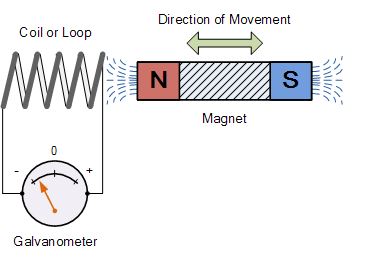
Likewise, if the magnet is now held stationary and ONLY the coil is moved towards or away from the magnet the needle of the galvanometer will also deflect in either direction. Then the action of moving a coil or loop of wire through a magnetic field induces a voltage in the coil with the magnitude of this induced voltage being proportional to the speed or velocity of the movement.
Then we can see that the faster the movement of the magnetic field the greater will be the induced emf or voltage in the coil, so for Faraday’s law to hold true there must be “relative motion” or movement between the coil and the magnetic field and either the magnetic field, the coil or both can move.
If we were able to move the magnet in the diagram above in and out of the coil at a constant speed and distance without stopping we would generate a continuously induced voltage that would alternate between one positive polarity and a negative polarity producing an alternating or AC output voltage and this is the basic principle of how an electrical generator works similar to those used in dynamos and car alternators.
In small generators such as a bicycle dynamo, a small permanent magnet is rotated by the action of the bicycle wheel inside a fixed coil. Alternatively, an electromagnet powered by a fixed DC voltage can be made to rotate inside a fixed coil, such as in large power generators producing in both cases an alternating current.
Lenz’s Law of Electromagnetic Induction
Faraday’s Law tells us that inducing a voltage into a conductor can be done by either passing it through a magnetic field, or by moving the magnetic field past the conductor and that if this conductor is part of a closed circuit, an electric current will flow. This voltage is called an induced emf as it has been induced into the conductor by a changing magnetic field due to electromagnetic induction with the negative sign in Faraday’s law telling us the direction of the induced current (or polarity of the induced emf).
But a changing magnetic flux produces a varying current through the coil which itself will produce its own magnetic field as we saw in the Electromagnets tutorial. This self-induced emf opposes the change that is causing it and the faster the rate of change of current the greater is the opposing emf. This self-induced emf will, by Lenz’s law oppose the change in current in the coil and because of its direction this self-induced emf is generally called a back-emf.
Lenz’s Law states that: ” the direction of an induced emf is such that it will always opposes the change that is causing it”. In other words, an induced current will always OPPOSE the motion or change which started the induced current in the first place and this idea is found in the analysis of Inductance.
Likewise, if the magnetic flux is decreased then the induced emf will oppose this decrease by generating and induced magnetic flux that adds to the original flux.
Lenz’s law is one of the basic laws in electromagnetic induction for determining the direction of flow of induced currents and is related to the law of conservation of energy.
According to the law of conservation of energy which states that the total amount of energy in the universe will always remain constant as energy cannot be created nor destroyed. Lenz’s law is derived from Michael Faraday’s law of induction.
One final comment about Lenz’s Law regarding electromagnetic induction. We now know that when a relative motion exists between a conductor and a magnetic field, an emf is induced within the conductor.
But the conductor may not actually be part of the coils electrical circuit, but may be the coils iron core or some other metallic part of the system, for example, a transformer. The induced emf within this metallic part of the system causes a circulating current to flow around it and this type of core current is known as an Eddy Current.
Eddy currents generated by electromagnetic induction circulate around the coils core or any connecting metallic components inside the magnetic field because for the magnetic flux they are acting like a single loop of wire. Eddy currents do not contribute anything towards the usefulness of the system but instead they oppose the flow of the induced current by acting like a negative force generating resistive heating and power loss within the core. However, there are electromagnetic induction furnace applications in which only eddy currents are used to heat and melt ferromagnetic metals.
Transformer:
There is an effect of electromagnetism known as mutual induction, whereby two or more coils of wire placed so that the changing magnetic field created by one induces a voltage in the other. If we have two mutually inductive coils and we energize one coil with AC, we will create an AC voltage in the other coil. When used as such, this device is known as a transformer:
Eddy Currents Circulating in a Transformer
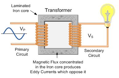
The changing magnetic flux in the iron core of a transformer above will induce an emf, not only in the primary and secondary windings, but also in the iron core. The iron core is a good conductor, so the currents induced in a solid iron core will be large. Furthermore, the eddy currents flow in a direction which, by Lenz’s law, acts to weaken the flux created by the primary coil.
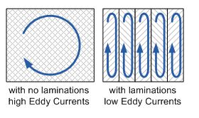
Laminating the Iron Core
Eddy current and hysteresis losses cannot be eliminated completely, but they can be greatly reduced. Instead of having a solid iron core as the magnetic core material of the transformer or coil, the magnetic path is “laminated”.
These laminations are very thin strips of insulated (usually with varnish) metal joined together to produce a solid core. The laminations increase the resistance of the iron-core thereby increasing the overall resistance to the flow of the eddy currents, so the induced eddy current power-loss in the core is reduced, and it is for this reason why the magnetic iron circuit of transformers and electrical machines are all laminated.
The relationship between the primary windings and secondary windings has a useful mechanical analogy, using torque and speed to represent voltage and current, respectively:
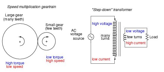
Speed multiplication gear train steps torque down and speed up. Step-down transformer steps voltage down and current up.
If the winding ratio is reversed so that the primary coil has less turns than the secondary coil, the transformer “steps up” the voltage from the source level to a higher level at the load:
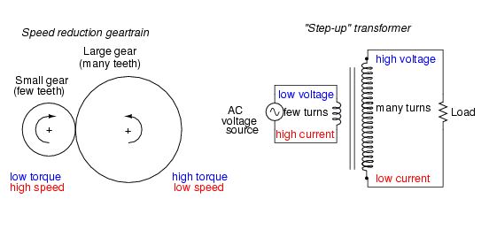
Speed reduction gear train steps torque up and speed down. Step-up transformer steps voltage up and current down.
Electrical resistance:
The electrical resistance of an electrical conductor is a measure of the difficulty of passing an electric current through a substance. It explains the relationship between voltage (amount of electrical pressure) and the current (flow of electricity). With more resistance in a circuit, less electricity will flow through the circuit. The inverse of resistance is conductance, a measure not much used. All objects have some resistance, except superconductors.
Resistance, discovered by Georg Simon Ohm in 1827, is the ratio between voltage and current. Ohm’s law said that the voltage between any two points in a conductor changes directly as the current between the two points, given the temperature remains the same. He described it with the equation:
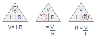
Where:
V= voltage.
R= Resistance.
I= Current in Amperes.
Practical application of Ohms law.
The application of Ohms law within Broughton Electro-Air products applies only to resistive heating elements as used in our industrial fan heaters, and cable specifications.
Resistance does not apply in the same way for the technical characteristics of motors, pumps, contactors, etc. These components operate using the principles of induction and capacitance which will be covered later in this hand book. A combination of resistance, inductance and capacitance is called impedance. These are all effects that impede the flow of current through a circuit.
 Reading using a multi-meter set to Ω.
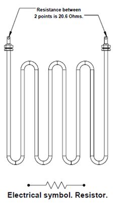
This is one of our standard resistive heating elements, as used in our industrial fan heaters. The purpose of it within our fan haters is to utilise the effects of resistance to produce heat.
The resistance between the terminals is 20.6Ω. This is a 230v element. Using the formula above we can work out how much current this element will draw.
I = V / R
230v/ 20.6 = 11.16A.
It should be noted that for safety purposes and adherence to EN 60335 our products need to be tested, and safe, at a supply voltage of 1.06 times the rated voltage.
This would give us a voltage of 243.8v.
243.8 / 20.6 = 11.83A
This can make a significant difference on more powerful machines.
Another standard heating element that is used looks exactly the same as the example above. However, this element is intended for an 110v fan heater and has a resistance of 4.6Ω between the terminals. If this part was incorrectly fitted to our 230v machine and we apply Ohms law we find the following:
230v/ 4.6 = 50A.
The machine would now draw 50 Amps.
This would have serious safety implications for the cables and protective devices.
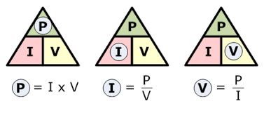
Power formula:
We can now apply the power formula to work out how many Watts this will produce:
 Power formula.
Where:
P= Power in Watts.
I = Current in Amperes.
V = Voltage.
IXV=P
11.16 X 230=2566.8 Watts. (2.57kW).
Resistance and cable safety:
A sound circuit will offer as little resistance as practicably possible between the components of that circuit. All copper cable has resistance but this is very low. Poor cable terminations and connections at components can increase this resistance. As the example above shows, this will create heat where it is not required or desirable. (See the electrical safety handbook for examples of this).
Long cable runs will also increase the resistance of the cable and cause a voltage drop. This equates to a loss of energy in the form of heat.
Voltage drop is the decrease of electrical potential along the path of a current flowing in an electrical circuit. Voltage drops in the internal resistance of the source, across conductors, across contacts, and across connectors are undesirable because some of the energy supplied is dissipated. The voltage drop across the electrical load is proportional to the power available to be converted in that load to some other useful form of energy.
For example, an electric fan heater may have a resistance of ten ohms, and the wires that supply it may have a resistance of 0.2 ohms, about 2% of the total circuit resistance. This means that approximately 2% of the supplied voltage is lost in the wire itself. An excessive voltage drop may result in the unsatisfactory performance of a space heater and overheating of the wires and connections.
When specifying cables the manufacturers cable data should always be followed.
Exercise. Resistance, voltage drop and power loss:
It can be easier to view a circuit as a series of resistors. R1 being the cable, R2 being the design load or element and R3 being the cable.
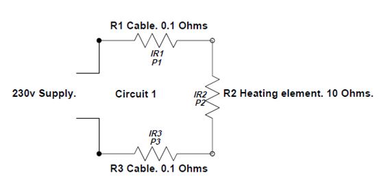
The total resistance of this circuit is R1+R2+R3.
0.1Ω + 10Ω + 0.1Ω = 10.2Ω
How do we calculate the following (Circuit 1)?
a) Total current drawn by the circuit.
b) The voltage drop across each resistor.
c) The power dissipated by each resistor.
a) Total current drawn by the circuit.
Using Ohms law we can calculate the total current.
R1 + R2 + R3 = 10.2Ω
230v/ 10.2Ω = 22.55A
b) The voltage drop across each resistor. (IR drop)
IR1 = (22.55A) x (0.1Ω) = 2.255v
IR2 = (22.55A) x (10Ω) = 225.5v
IR3 = (22.55A) x (0.1Ω) = 2.255v
The 3 IR drops should total the supply voltage = 230v
c) The power dissipated by each resistor (P).
P1 = I2R1 = (22.55A)2 x (0.1Ω) = 50.85 Watts.
P2 = I2R2 = (22.55A)2 x (10.0Ω) = 5085 Watts.
P3 = I2R2 = (22.55A) 2 x (0.1Ω) = 50.85 Watts.
THIS SHOWS THAT THE CABLES ARE EMITTING 50.85 WATTS IN THE FORM OF HEAT.
IT SHOULD BE NOTED THAT THIS IS AN EXAMPLE. WE WOULD NORMALLY EXPECT A MUCH LOWER RESISTANCE ON THE CABLES!
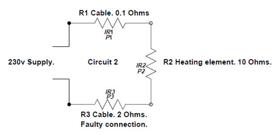
Exercise. Calculations on a faulty circuit.
Below is a circuit with a faulty connection (R3).
Calculate the following:
a) Total current drawn by the circuit.
b) The voltage drop across each resistor.
c) The power dissipated by each resistor.
a) Total current drawn by the circuit.
——————————————————————
——————————————————————
b) The voltage drop across each resistor. (IR drop)
IR1 = ——————————————–
IR2 = ——————————————–
IR3 = ——————————————–
c) The power dissipated by each resistor (P).
P1 = I2R1 = ———————————————-
P2 = I2R2 = ———————————————-
P3 = I2R2 = ———————————————-
Major Features of Resistors in Series
1. Series resistances add: Rs = R1 + R2 + R3 +….
2. The same current flows through each resistor in series.
3. Individual resistors in series do not get the total source voltage, but divide it.
Impedance:
Electrical impedance, measure of the total opposition that a circuit or a part of a circuit presents to electric current. Impedance includes both resistance and reactance. The resistance component arises from collisions of the current-carrying charged particles with the internal structure of the conductor. The reactance component is an additional opposition to the movement of electric charge that arises from the changing magnetic and electric fields in circuits carrying alternating current. Impedance reduces to resistance in circuits carrying steady direct current.
The magnitude of the impedance Z of a circuit is equal to the maximum value of the potential difference, or voltage, V (volts) across the circuit, divided by the maximum value of the current I (amperes) through the circuit, or simply Z = V/I. The unit of impedance, like that of resistance, is the ohm. Depending on the nature of the reactance component of the impedance (whether predominantly inductive or capacitive), the alternating current either lags or leads the voltage.
Reactance:
Reactance, in electricity, is the measure of the opposition that a circuit or a part of a circuit presents to electric current insofar as the current is varying or alternating. Steady electric currents flowing along conductors in one direction undergo opposition called electricalresistance, but no reactance. Reactance is present in addition to resistance when conductors carry alternating current.
Reactance is of two types: inductive and capacitive. Inductive reactance is associated with the magnetic field that surrounds a wire or a coil carrying a current. An alternating current in such a conductor, or inductor, sets up an alternating magnetic field that in turn affects the current in, and the voltage (potential difference) across, that part of the circuit. An inductor essentially opposes changes in current, making changes in the current lag behind those in the voltage. The current builds up as the driving voltage is already decreasing, tends to continue on at maximum value when the voltage is reversing its direction, falls off to zero as the voltage is increasing to maximum in the opposite direction, and reverses itself and builds up in the same direction as the voltage even as the voltage is falling off again. Inductive reactance, a measure of this opposition to the current, is proportional to both the frequency f of the alternating current and a property of the inductor called inductance (symbolized by L and depending in turn on the inductor’s dimensions, arrangement, and surrounding medium). Inductive reactance XL equals 2π times the product of the frequency of the current and the inductance of the conductor, simply XL = 2πfL. Inductive reactance is expressed in ohms. (The unit of frequency is hertz, and that of inductance is henry.)
Capacitive reactance, on the other hand, is associated with the changing electric field between two conducting surfaces (plates) separated from each other by an insulating medium. Such a set of conductors, a capacitor, essentially opposes changes in voltage, or potential difference, across its plates. A capacitor in a circuit retards current flow by causing the alternating voltage to lag behind the alternating current, a relationship in contrast to that caused by an inductor. The capacitive reactance, a measure of this opposition, is inversely proportional to the frequency f of the alternating current and to a property of the capacitor called capacitance (symbolized by C and depending on the capacitor’s dimensions, arrangement, and insulating medium). The capacitive reactance XC equals the reciprocal of the product of 2π, the frequency of the current, and the capacitance of that part of the circuit, simply XC = 1/(2πfC). Capacitive reactance has units of ohms. (The unit of capacitance is farad.)
3 phase electrical supply:
Multiphase AC Generators
With the standard UK domestic 230V 13A supply you’re limited to a maximum of 3kW heat, so in order to accommodate the higher output fan haters we use three phase 400V three phase.
A generator can be manufactured with a different number of the coils placed in the stator. One coil in the stator forms a single-phase generator, while several coils make up a multiphase generator. An EMF with equal amplitude is induced in each coil.
The general advantages of a multiphase generator over a single-phase generator with equal power is that the former is smaller, lighter and less expensive. Basically the only physical difference between a single generator and a multiphase generator is the additional coils with accompanying parts in the stator. Each phase generates approximately equal amounts of energy. The generated energy will be multiplied with the number of phases (i.e., installed coils in the generator).
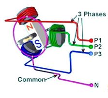 Simple 3 phase generator. 3 coils in the stator.
![]() Electrical symbol. Inductor.
Electrical symbol. Inductor.
The magnetic field rotates together with the rotor magnet. The EMF induced in each stator coil has the same amplitude and frequency (phase shifted for 120°).
Those three induced EMFs represent the three phases. The coils are physically shifted 120˚ from each other. Basically, the generator construction and its working principle define the shape and the induced voltage value. The common rotor rotates with equal speed, and thus the frequency values of all induced voltages are equal as well.
In the UK and Europe the rotor rotates at 50 times per second. This is the frequency and is measured in Hertz. Hz. The frequency in the UK and Europe is 50 Hz.
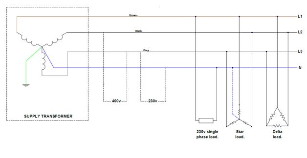
Electricity is transmitted at voltages of up to 400,000v. It is stepped down using transformers to 230v single for domestic consumption and 400v 3 phase for light industrial/ commercial consumption.
It is necessary for all three induced EMFs to be even, with equal phase displacement between them. This represents the symmetrical three-phase system.
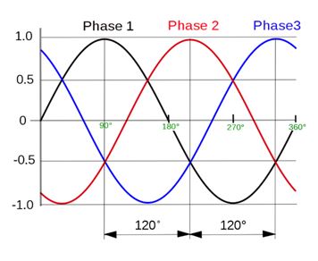
3 phase wave form with a displacement of 120⁰.
Three-Phase Loads:
An electrical system is comprised of three main parts: energy generation, energy transmission and energy consumers. The consumers are the loads connected to the electrical system. One of the advantages of a three-phase system is that it can supply both single-phase and three-phase loads. The latter can be connected in a star (YN) or delta (D) connection. The diagram below showcases different variations of load connected to the three-phase system.

IL= (VL/ 1.73)/R= VP/RIL= (VL/R) X 1.73
Where:
IP= phase current.
IL= Line current.
VP= Phase voltage.
VL= Line voltage.
W= Watts.
Here at Broughton EAP we have four decades worth of experience in the design, manufacture and supply or portable air conditioning units, industrial electric fan heaters, refrigerant dehumidifiers and cooling and ventilation fans. Over the years we’ve worked with the countries leading climate control hire specialists, famous drinks manufacturers, large data centre’s and even local village halls, and we like to think everything we’ve learnt working with that diverse group is what gives us an edge. Not only can we deal with the specialists but we’re also happy looking after the smaller client whose application might not be huge but is still just as important.
For full details on our range of portable air conditioning units, industrial electric fan heaters, dehumidifiers and ventilation fans please visit our website, call +44 (0) 1527 830610 or email sales@broughtoneap.co.uk